1.Direct keypad actions
Shorcuts in Dibac
Most frequently used keys in Dibac cad
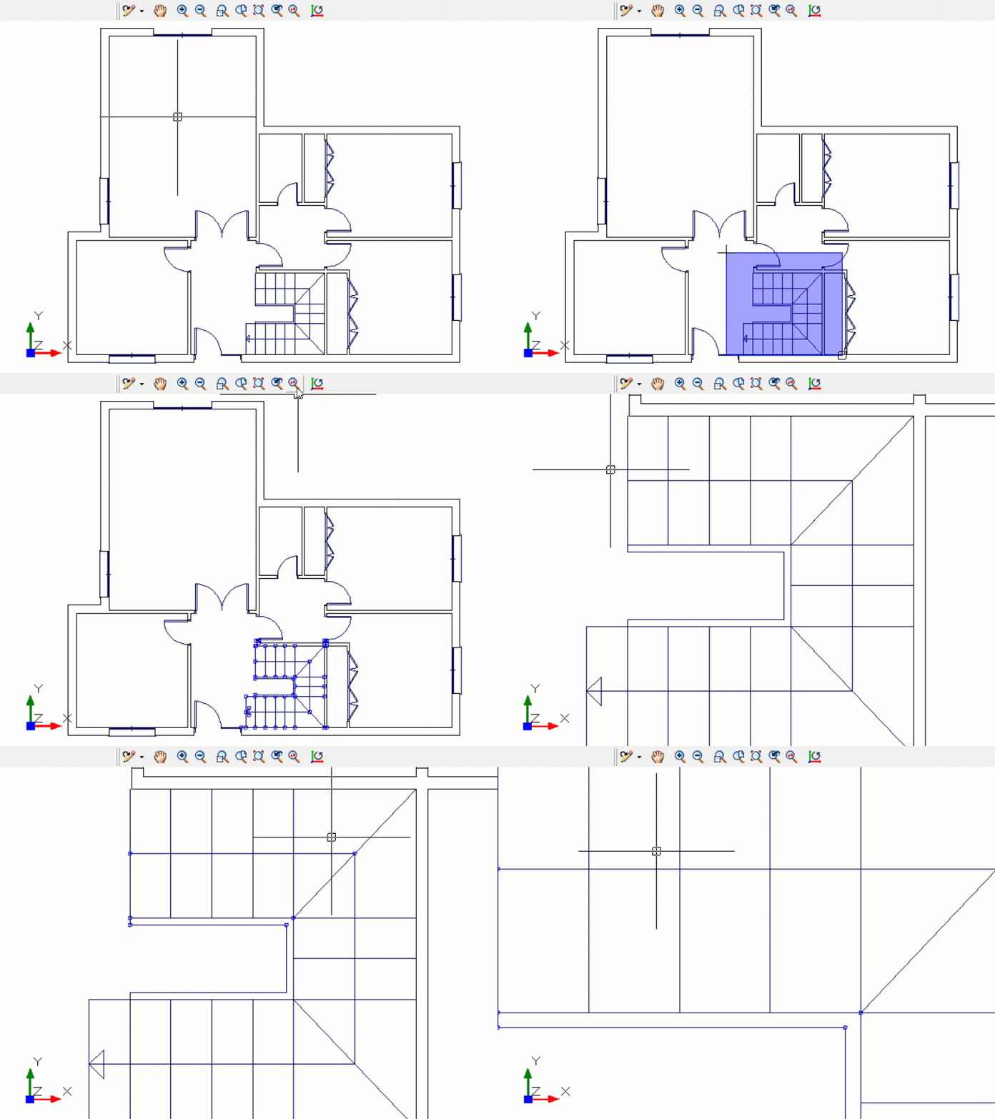
Zoom window
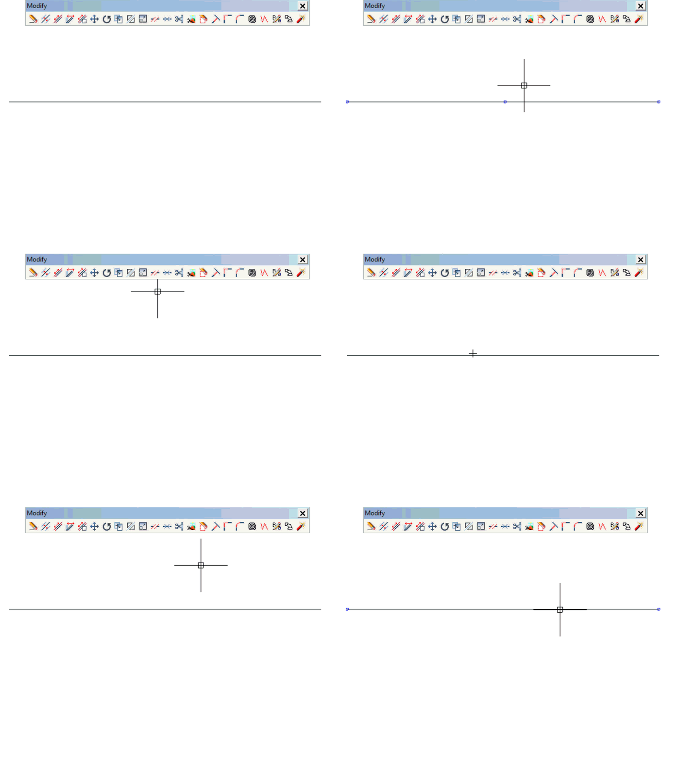
Zooms to display an area specified by a rectangular window. After pressing F2 click once on the top left corner of the area to be zoomed into, drag the pointer diagonally and click the opposite corner of the zoom area.
Extended zoom
Adjusts the magnification of the drawing area to accommodate the extents of all visible objects in the drawing.
Toggle Grid
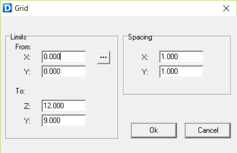
When F7 is pressed, the current activated grid appears. (Grid option in the Format menu). Press F7 again and it disappears
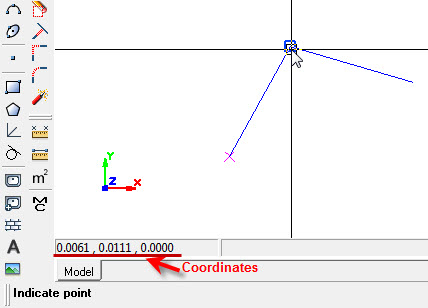
Coordinates
The following show the way to introduce coordinates
Relative to the origin (0,0)
Cartesian
Polar
x-coordinate; y-coordinate
radius<angle
Relative to the cursor
Cartesian
Polar
@x-coordinate; y-coordinate
@radius<angle
2.1.User Interface toolbars
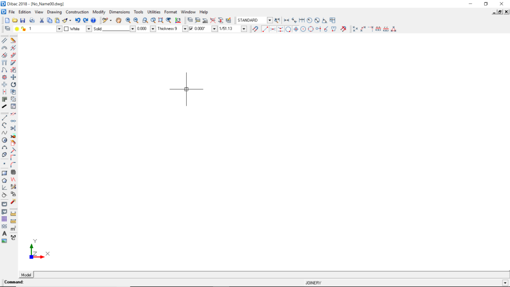
Program bar
This bar is at the very top of the screen, with the program name and location of the current drawing file.
Context menu bar
By clicking on these options, each one will expand its own commands
Standard toolbar
[New file] · [Open file] · [Save as] · [Print] · [Cut] · [Copy] · [Paste] · [Match properties] · [Undo] · [Redo] · [Help]
View toolbar
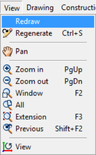
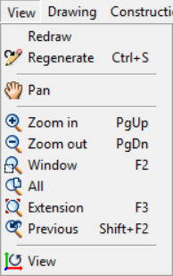
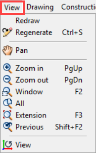
[Regenerate] · [Pan] · [Zoom in] · [Zoom out] · [Window Zoom] · [Zoom all] · [Zoom extent] · [Previous zoom] · [View]
Dimensions toolbar
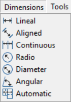
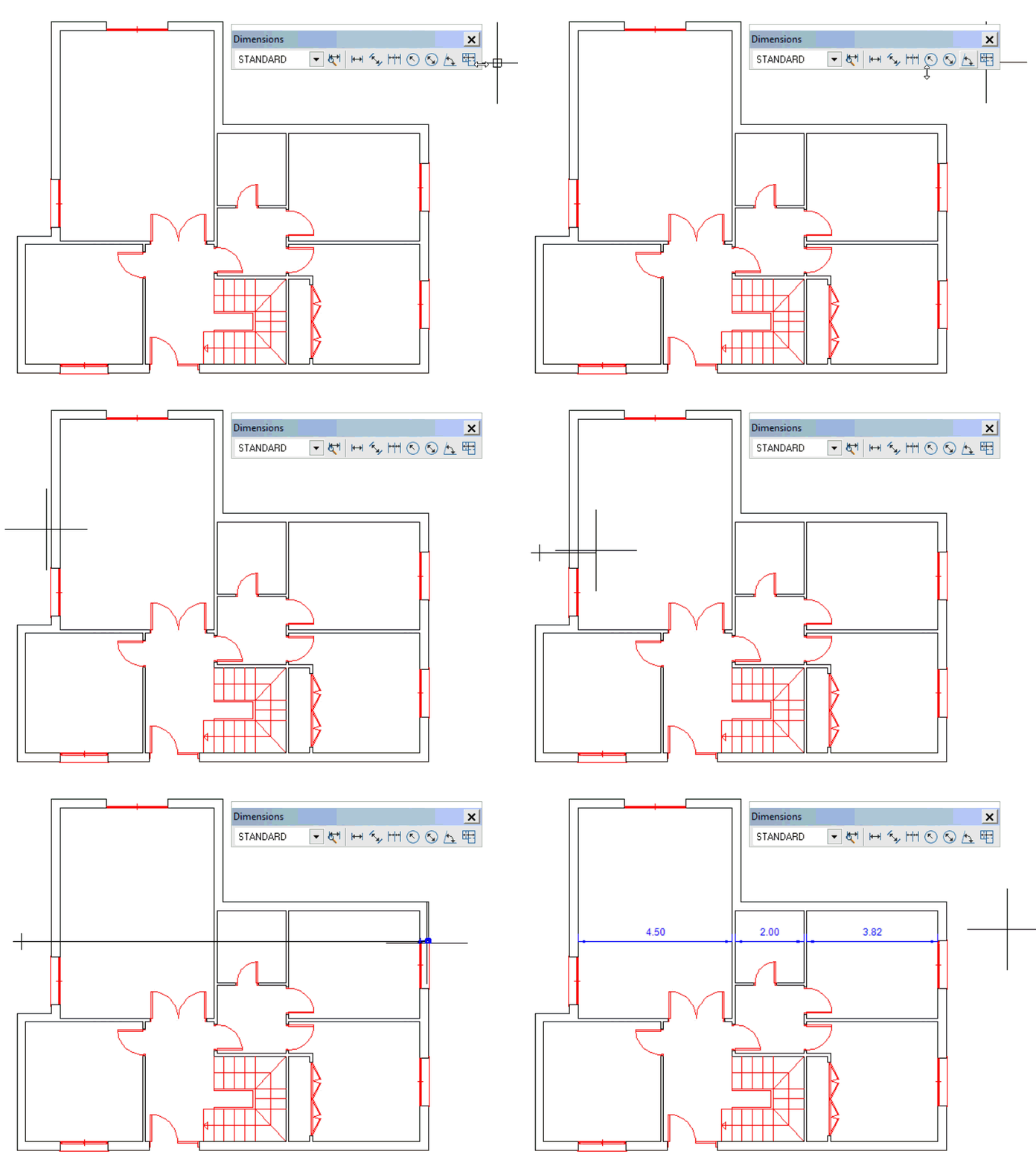
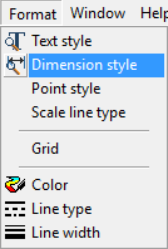
[Dimension style] · [New style] · [Linear dimension] · [Aligned dimension] · [Continued dimension] · [Radius] · [Diameter] · [Angle] · [Automatic dimension]
Guides toolbar
[Arbitrary] · [Distance] · [Intersection] · [Equidistance] · [Maximum distance] · [Triangulation]
Properties toolbar
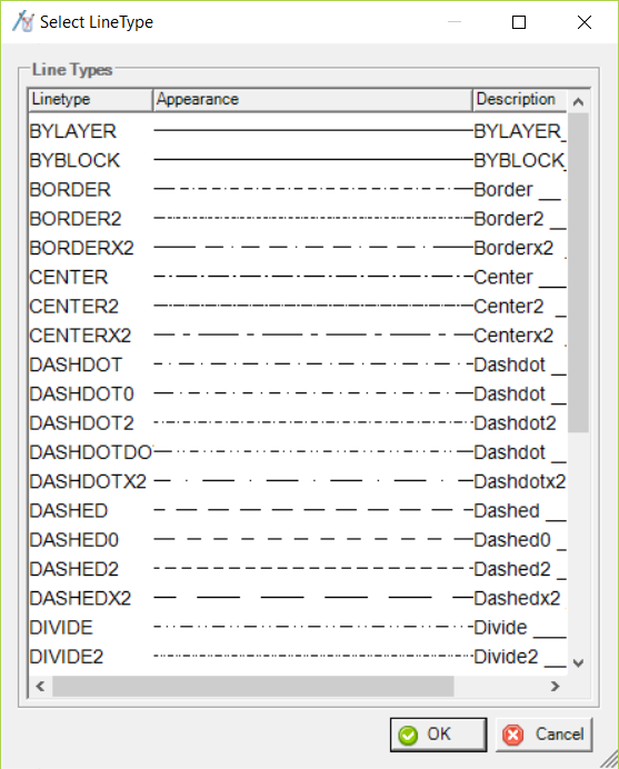
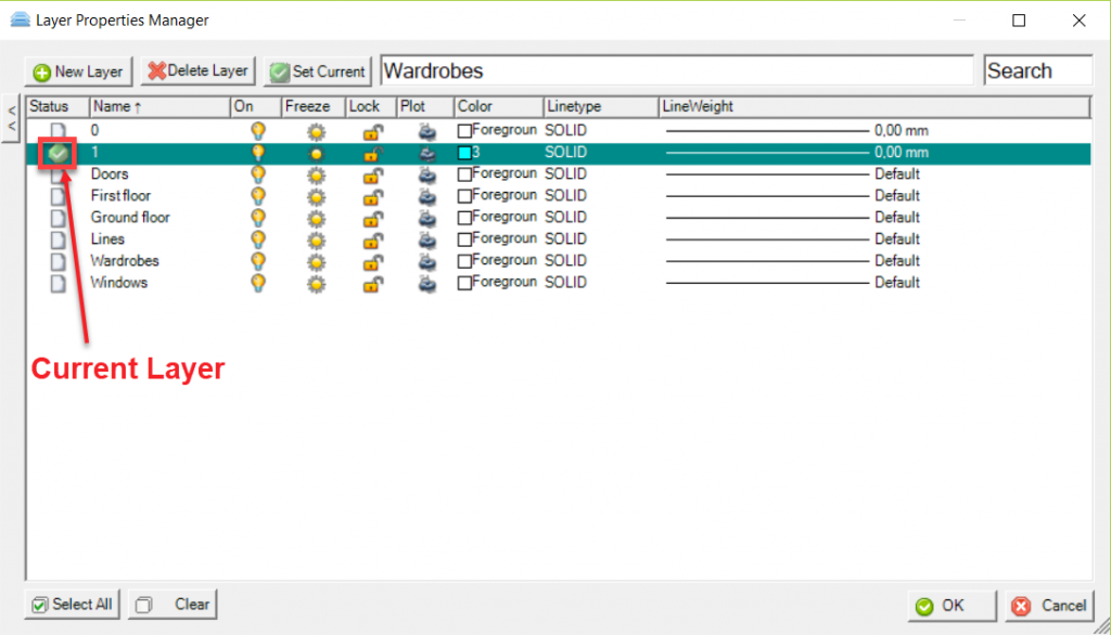
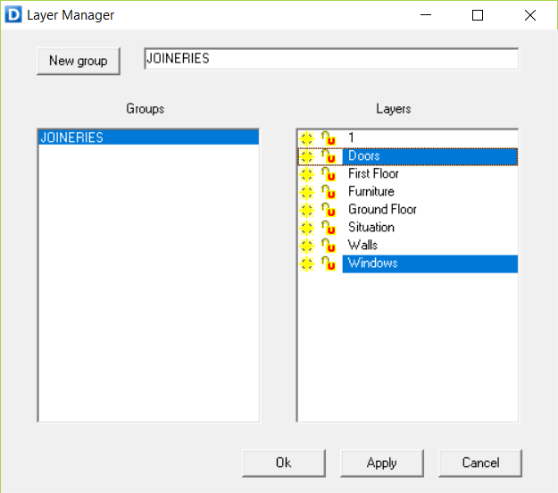
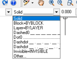
[Layers] · [Layer Manager] · [Color] · [Line type] · [Line width] · [Wall thickness] · [H/V (Horizontal – Vertical) (Ortho mode)] · [Scale]
Object Snap toolbar
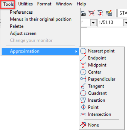
[Running objects snap] · [Endpoint] · [Intersection] · [Midpoint] · [Nearest Point] · [Node] · [Center] · [Quadrant] · [Perpendicular] · [Tangent] · [Block insertion] · [None]
Functions menu toolset
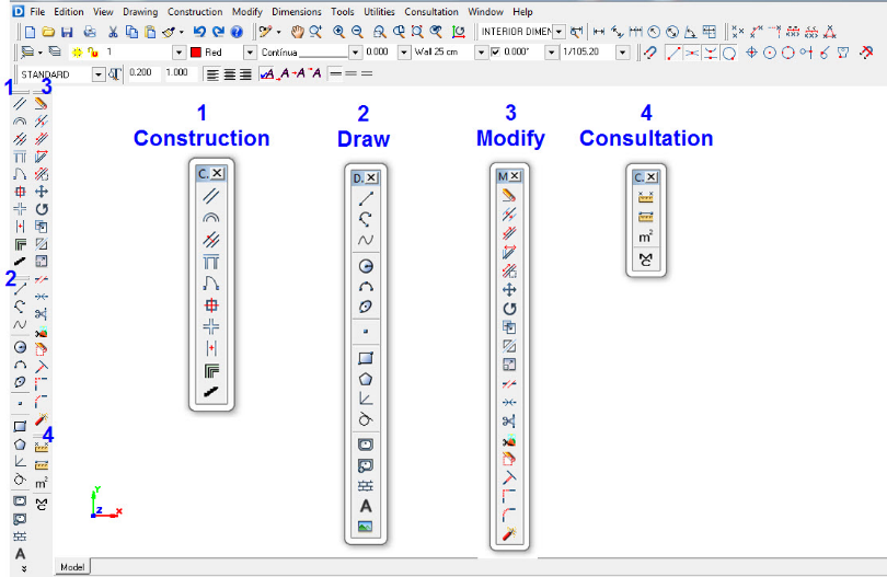
This large toolset appears in two columns on the left-hand side of the screen.
It consists of 4 function toolbars:
-
[CONSTRUCTION]
-
[MODIFY]
-
[DRAW]
-
[CONSULTATION]
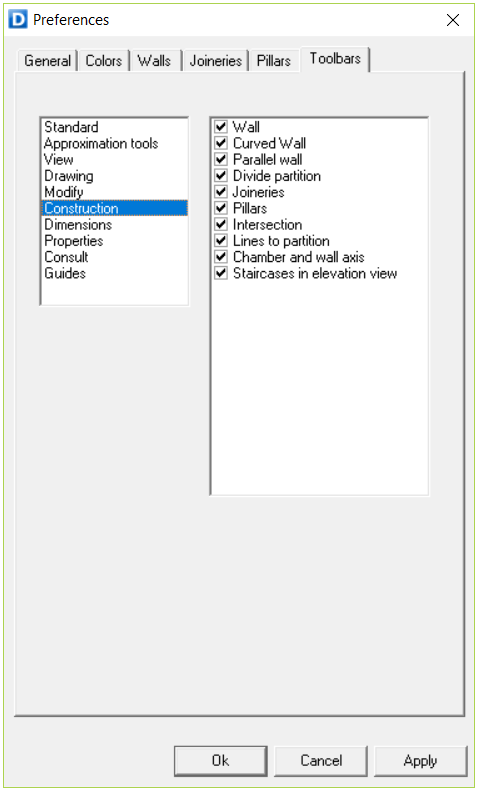
These toolbars can be moved to any part of the screen.
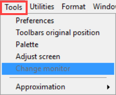
To return them to the original position, select the [Original position] option under the [Tools] menu or double-left click on the top of the toolbar.

TO ENTER A FUNCTION, click on it
TO EXIT A FUNCTION, right click or press the ESC key.

When not using a function, A RIGHT CLICK CAN ALSO RECOVER THE LAST FUNCTION USED and you can exit or enter this function by right clicking repeatedly
You can access “Help” with F1 at any time to obtain information about the function being used under “Help Topics” In the “Help” menu, you can access the Help index, change chapters or search for a specific concept.
2.2.User Interface functions
Pointer
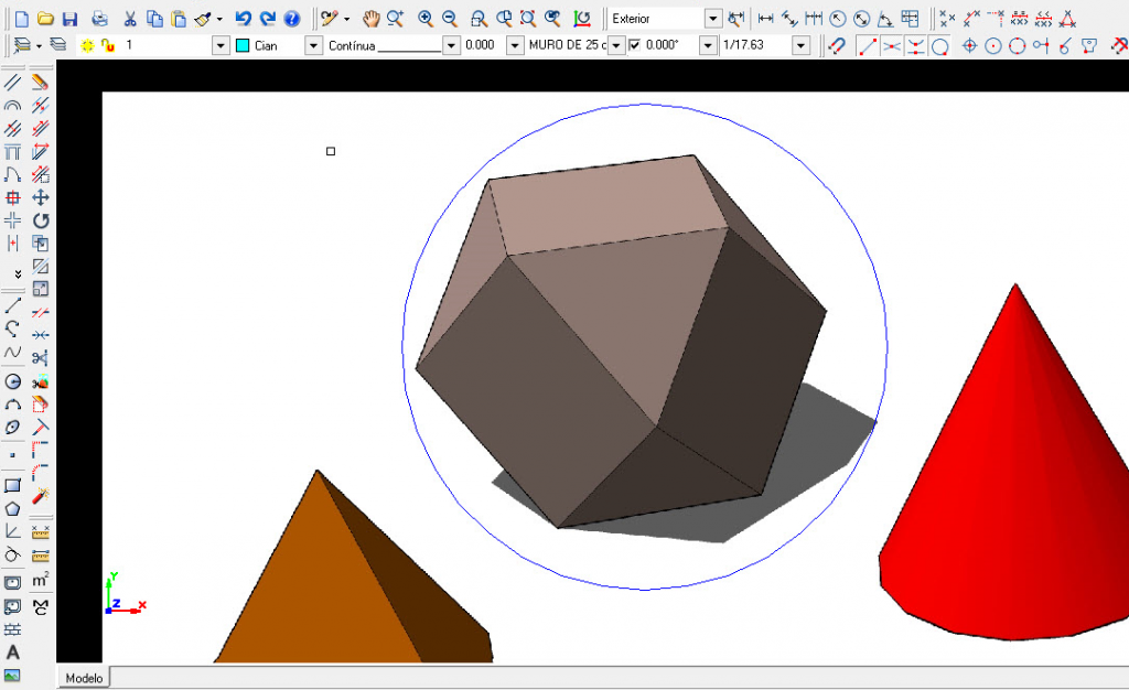
The cursor consists of two perpendicular lines (crosshair) and a pick-box at their intersection.
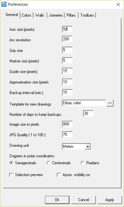
The size of the pointer lines can be changed as follow: [Tools] – [Preferences] – [General].
The first option is to change the [Crosshair] in pixels.
The penultimate option is to change the size of the pick-box [Approximation size in pixels], according to how precise you want it to be in acquiring items underneath it.
If you want to select and object, you must place the pick-box on that object. If there are several objects within the pick-box, it will select the first according to the order of priority established in the Object Snap.
You can see a preview of the selection by activating this option in [Tools] – [Preferences] – [General] – [Selection Preview]. This way the object to be selected with the pick-box will be highlighted beforehand.
Mouse
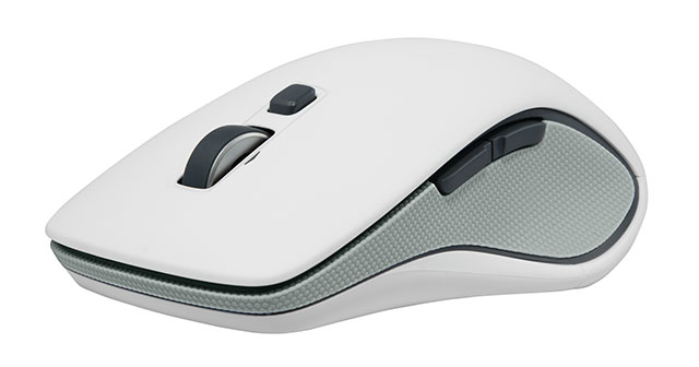
A two-button mouse with “Scroll” (Wheel) should be used.
The right button serves to exit functions (one click) and return to the last function (another click).
In case of deletion, after selecting the objects to be deleted, right click confirms the deletion.
H/V Ortho mode (F8)

Located on the Icon Bar (properties bar), this indicates the perpendicularity angle.

The checkbox activates and deactivates it. It can also be done by pressing the F8 key while the pointer is on an empty area of the drawing.
 When you press F8 with the pointer on an object (for example, a line or a wall) ortho mode is automatically activated by assigning the angle of the object.
Once activated, it forces the lines to be drawn perpendicular to the angle indicated in H/V. It also influences other functions like move, hatching and surface area by points, etc.

Deactivated H/V (not checked) indicates that the ortho mode is turned off.
Zoom. Changing the scale
Zoom options are under the [VIEW] menu.

F2 (WINDOW ZOOM)
Pressing the F2 key once and then clicking and simply dragging the mouse defines a visualization rectangle. Click the mouse again and the drawing area will appear on the screen.
F3 (ZOOM EXTENT).
Pressing F3 zooms to display the maximum extents of all objects .
SHIFT + F2
Pressing recovers the drawing at the immediately previous scale re-doing the camera actions.
Undo. Go back step by step.
By pressing the CTRL+ Z keys at any time, clicking on the “Undo” function from the toolbar, or clicking on the “Undo” option under the flyout menu on the tab “Edition”, you return to the previous state of the drawing. Consequently, you can go backwards as many times as you wish, up to the start of the drawing, as long as you have not activated the “Purge” function in the flyout menu of the “File” tab.
Virtual functions menu
This allows you to access functions without going through the menu, thus considerably shortening the time spent drawing.
If no function is selected (which happens after the ESC key is pressed) and you DOUBLE CLICK on any object in the drawing, you will automatically activate the corresponding function of that object, with all of its characteristics. So, if you click on a wall, you will continue to draw walls with the same thickness, color and line type of the selected object.
This can be done by just DOUBLE CLICKING on an object that has already been drawn. For example, if you want to make a straight line, double click on another previously drawn line. If you want to draw with a certain wall type, double click on a similar one
If you DOUBLE CLICK on text for the first time, you will be able to access to a dialog window where the text can be modified.
If you want to copy it, just click [OK].
If you want to modify, activate [Modify] option.
If you want to enter a new text with the same attributes, once the [Modify] option is deactivated, you can write whatever new text you want and it will be the same font, size, etc.
DOUBLE CLICK on a door to enter the “Doors” function. A type of door will appear, and you will be able to check and, in this case, change the width of the sash, whether it has a window, the number of sashes and the total length. Doors and windows will remain assigned “Centered inside” by default.
If you click on a pillar, as well as entering the same function, you will obtain its dimensions.
This allows you to see that the entire drawing acts as a Virtual Menu of functions, involving both frozen and current layers.
3.Construction toolbar
3.1.Walls
The WALL function includes wall attributes and partitions as well.
This command draws 2 straight parallel lines of a certain thickness, in which you can insert the joinery (doors, windows and wardrobes) very easily.
Thickness
The program uses a thickness of 25 cm. by default.
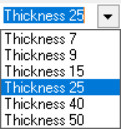
To use any other wall thickness, you can select it or type it directly in the [Wall thickness] located in the [Properties] toolbar.
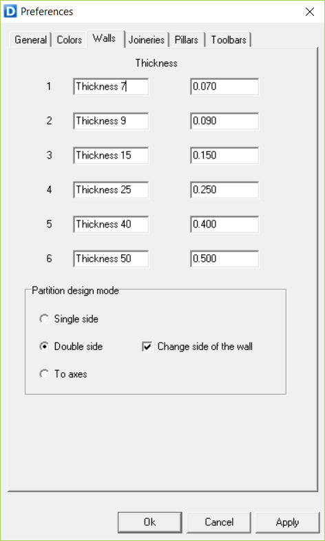
The name and thickness of these walls can be changed. To do this go to [Tools] > [Preferences] > [Walls].
The wall insertion edge can be changed by pressing the F5 key. Everytime you press it the insertion edge will shift from the interior to the exterior of the wall.
Drawing partitions
To draw a partition without a length measurement (rough sketch), click once on any point of the workspace. Now move the mouse cursor in the direction of the wall. You will see a flexible line indicated in the direction of the wall. To finalize this, click again.
Now, you are going to draw a partition 5 meters long and 25 cm thick:
- Check that the Wall thickness tab shows [Thickness 25].
- Click anywhere on the top left-hand side of the screen.
- Move the mouse to the right, and before clicking, type 5 (Enter). A double straight line, 5 meters long, will appear.
 To start at another point, right click to exit the function.
 Right click again to return to the function and draw another wall.
Ortho mode
A wall will be drawn using to the current orthogonal mode. However, if you want to draw a partition at 45º, H/V should be at 45º and the checkbox should be active.
On the other hand, if you have the H/V (ortho mode) checkbox unchecked, the partitions will be drawn according to the direction indicated with the mouse.
 You can toggle the ortho mode by pressing F8
Joining methods
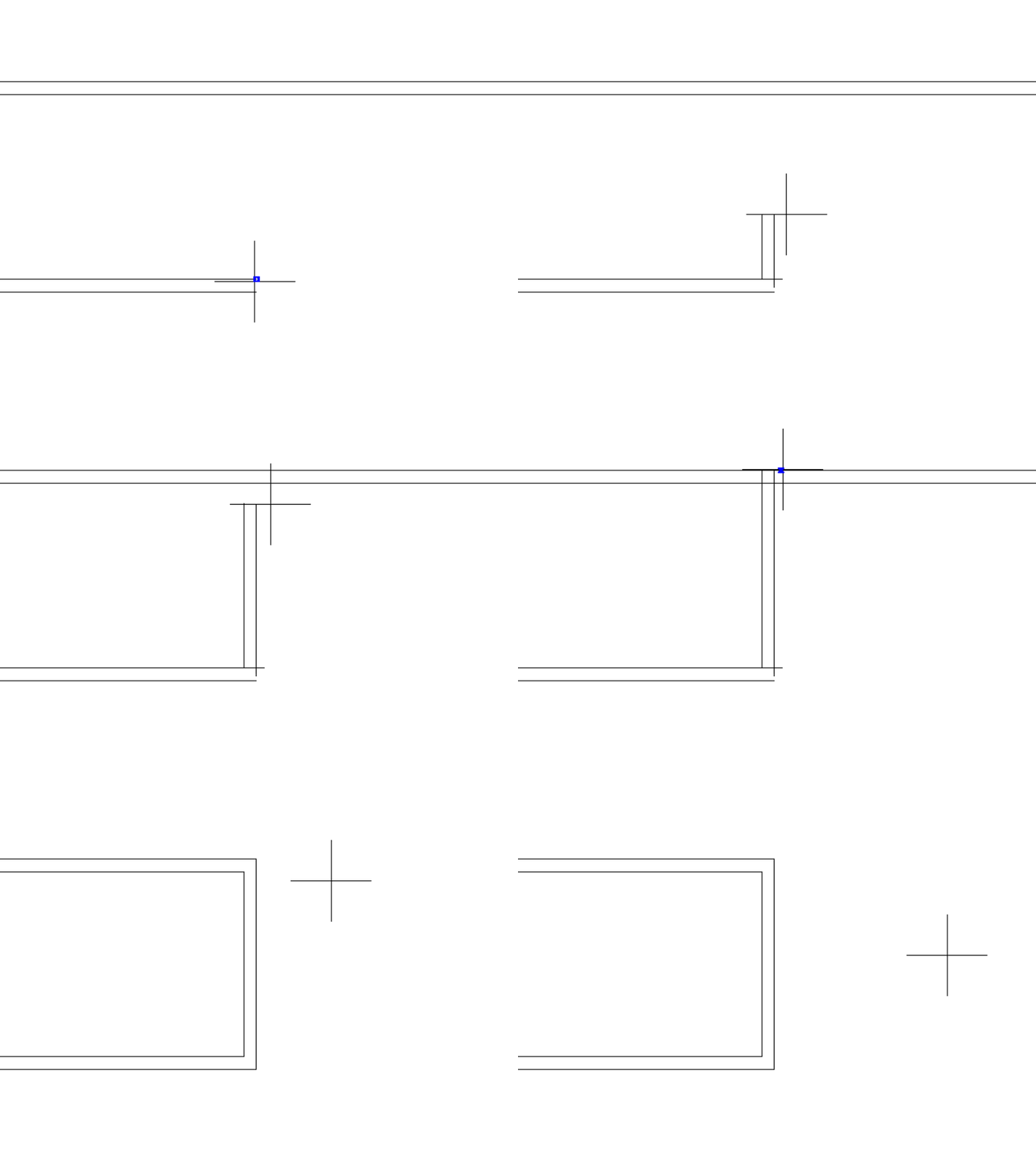
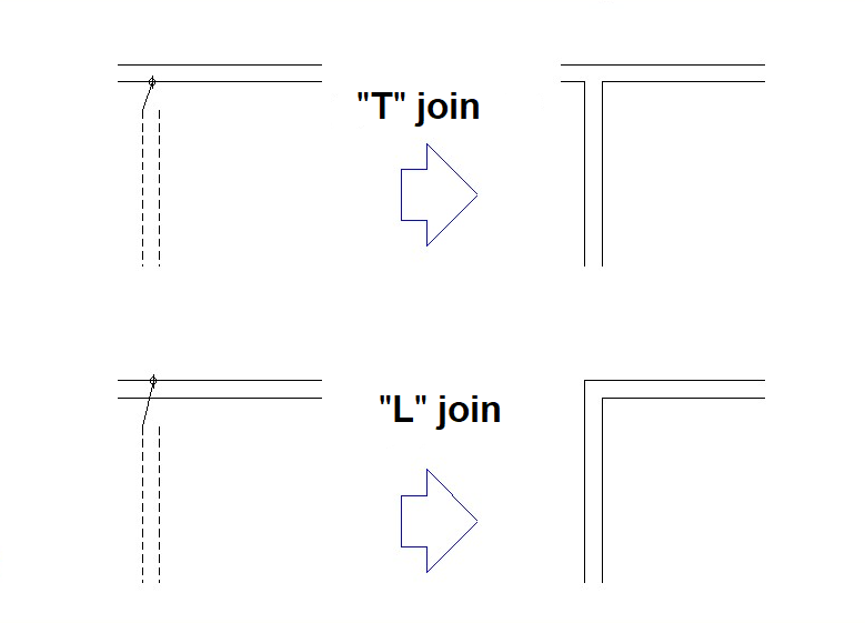
There are two joining methods with respect to the walls: “T” and “L”.
-
To make a type “T” intersection with another straight or curved partition, finish at the closest line of the two that constitute the wall
-
If you want to make an “L” intersection, click on the line furthest away from the two lines drawing the wall. In this way, you can create a corner
3.2.Curved walls
With this tool you can create walls and partitions made up of arcs. Most of the rules for drawing straight walls apply here.
To intersect another straight or curved partition, you will finish at the line closest to this partition if you want to make a “T” intersection, and if you click on the furthest line you will make an “L” intersection.
3.3.Parallel walls
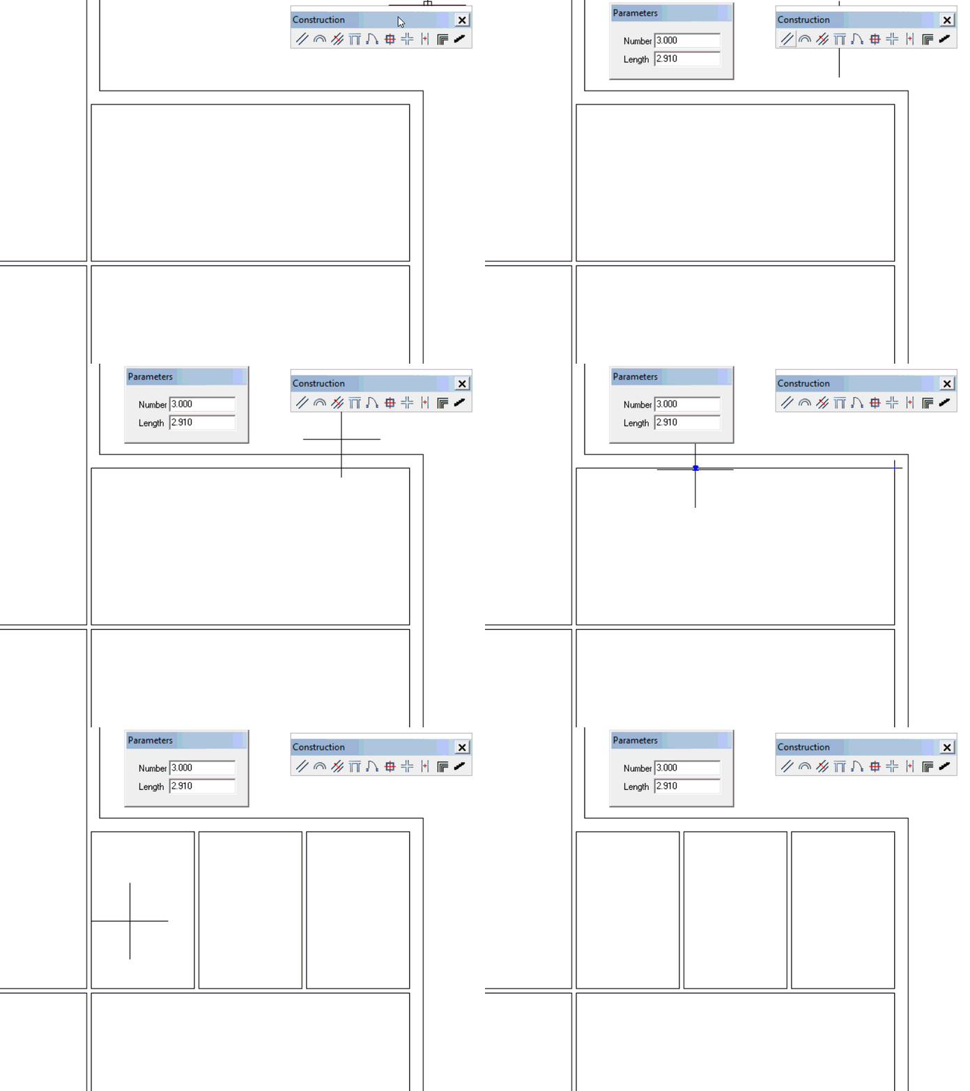
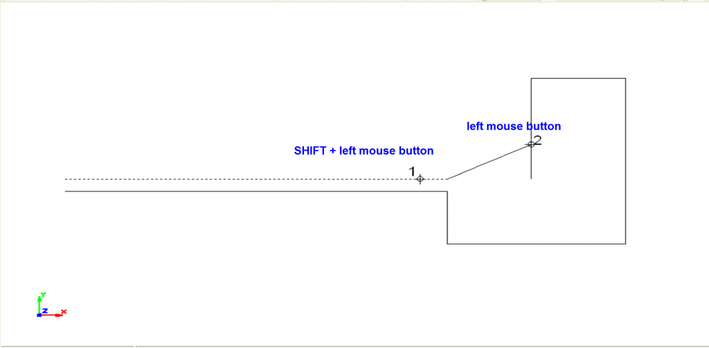
This tool allows you to create a parallel wall or partition at a certain distance from another one. To use this tool, you must follow these steps:
 Select the parallel wall function.
 Type the parallel distance. (By default, the program uses 1-meter parallel distance upon using the function for the first time).
 Press Enter.
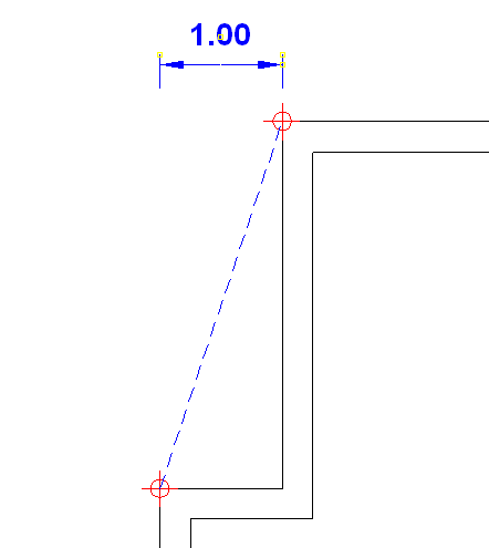
 Click on the line or arc of the reference wall to indicate from which point the parallel distance will be drawn (1).
 Then indicate on which side the parallel wall will be drawn by clicking once in that direction (2).
 Finally, click once again in the direction of the thickness of the parallel wall (3).
If you want to make another parallel wall at a different distance from the present one, you do not need to exit the function. Just type the new value and press ENTER.
To draw a centered partition with an axis, the distance will include the half of the partition thickness, with the position of the partition displayed on one side of the axis and the direction of the thickness on the other.
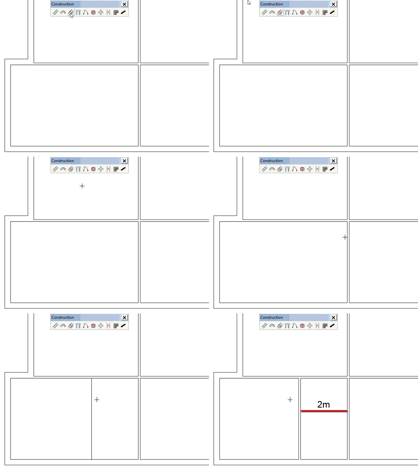
3.4.Divide wall
 Enter the function by clicking on the icon.
 Type the number of divisions
 Set the length of the perpendicular partitions
 Specify the first point of the wall and then the second point. The perpendicular partitions will be created by dividing the indicated distance between those two points, and to the left of the specified order
If you want to divide the wall with lines instead of partitions, hold the CTRL key while specifying the points.
3.5.Joinery
3.5.1.Doors
After selecting the “Joineries” icon, click on the DOORS tab.
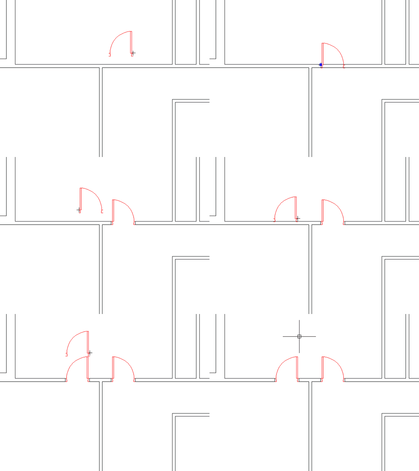
This function allows you to place doors or door openings onto any type of wall or partition (straight or curved). In the pop-up window you can set the door type, slab and frame size, opening angle and its position with respect to the thickness of the wall.
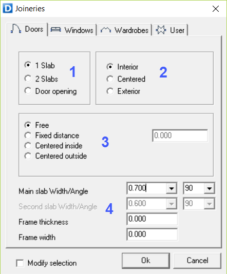
Within the door menu, there are 4 data entries:
 Number of slabs
You can select among 1 Slab [Single Door], 2 Slabs [Double Door] and Door opening
 Location on the wall
There are 4 options as regards where the door will be placed:
-
[FREE]. The “Free” option allows you to place the door on any part of the wall or partition, the hinge being the reference insertion point on the wall. The door symbol is highlighted in the position before being placed. If you want to change the opening direction before placing it, left click on an empty space.
-
[CENTERED OUTSIDE]. With the “Centered outside” option, the door will be drawn centered with respect to the opposite line that constitutes the partition, which is different from the one you click on to indicate the location of the door.
-
[FIXED DISTANCE]. When you select this option, a box appears to the right of the door where you can type a distance (in meters) from the closest intersection or corner. This option allows you to place the door hinge at a certain distance away from the corner closest to the door.
-
[CENTERED INSIDE]. With the “Centered inside” option active, the door will be drawn centered with respect to the partition line that you click on to place the door
 Door measurements and opening angles
-
[WIDTH/ANGLE of the Main Slab]. Two boxes appear on the right. The first is for the slab The second is for the opening angle of the slab.
-
[WIDTH/ANGLE Second slab]. This is activated when a double door is selected.
-
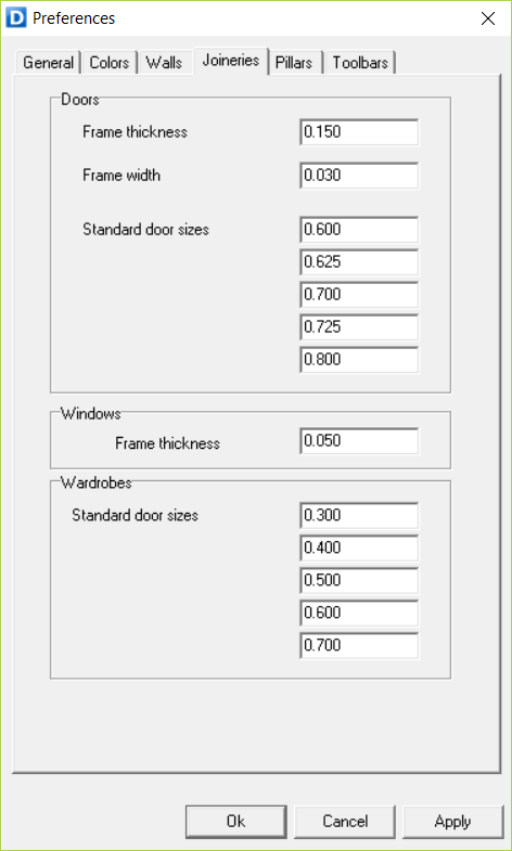
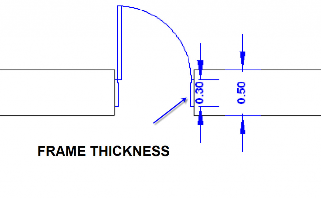
[FRAME THICKNESS]. This option refers to the frame dimension perpendicular to the wall.
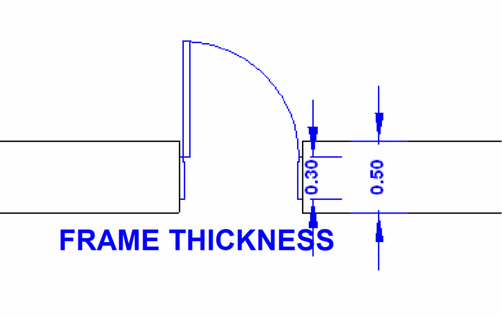
In this box you can type the thickness of the frame in meters.
The default dimension is 0.00, which makes the program automatically draw frames at 15 cm (0.15 m.) on any wall thicker than 15 cm.
When the wall is thinner than 15 cm, the program adjusts the frame to the wall thickness.
-
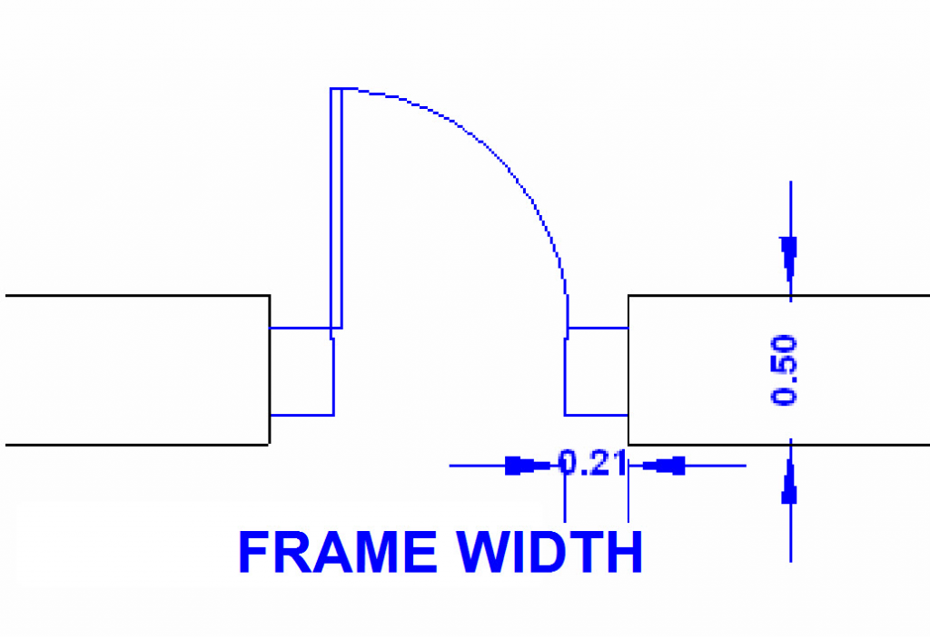
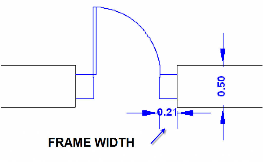
[FRAME WIDTH]. This option refers to the frame dimension in the longitudinal direction of the wall.
After setting the door parameters and pressing [OK], you can insert the door in the walls/partitions of the drawing. You can change the opening direction doing a left-click in an empty space of the drawing.
3.5.2.Windows
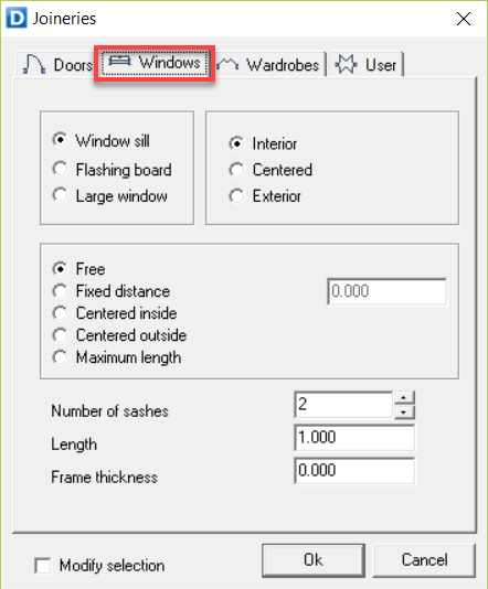
There are 4 headings under the Window menu:
1. Window type
-
[Window sill]: Creates a type of window WITHOUT a flashing board.
-
[Flashing board]: Creates a type of window WITH a flashing board.
-
[Large window]: Creates a large window for terrace doors.
2. Position on the wall thickness
Indicates the position of the window frame with respect to the wall width/thickness.
3. Location on the wall
-
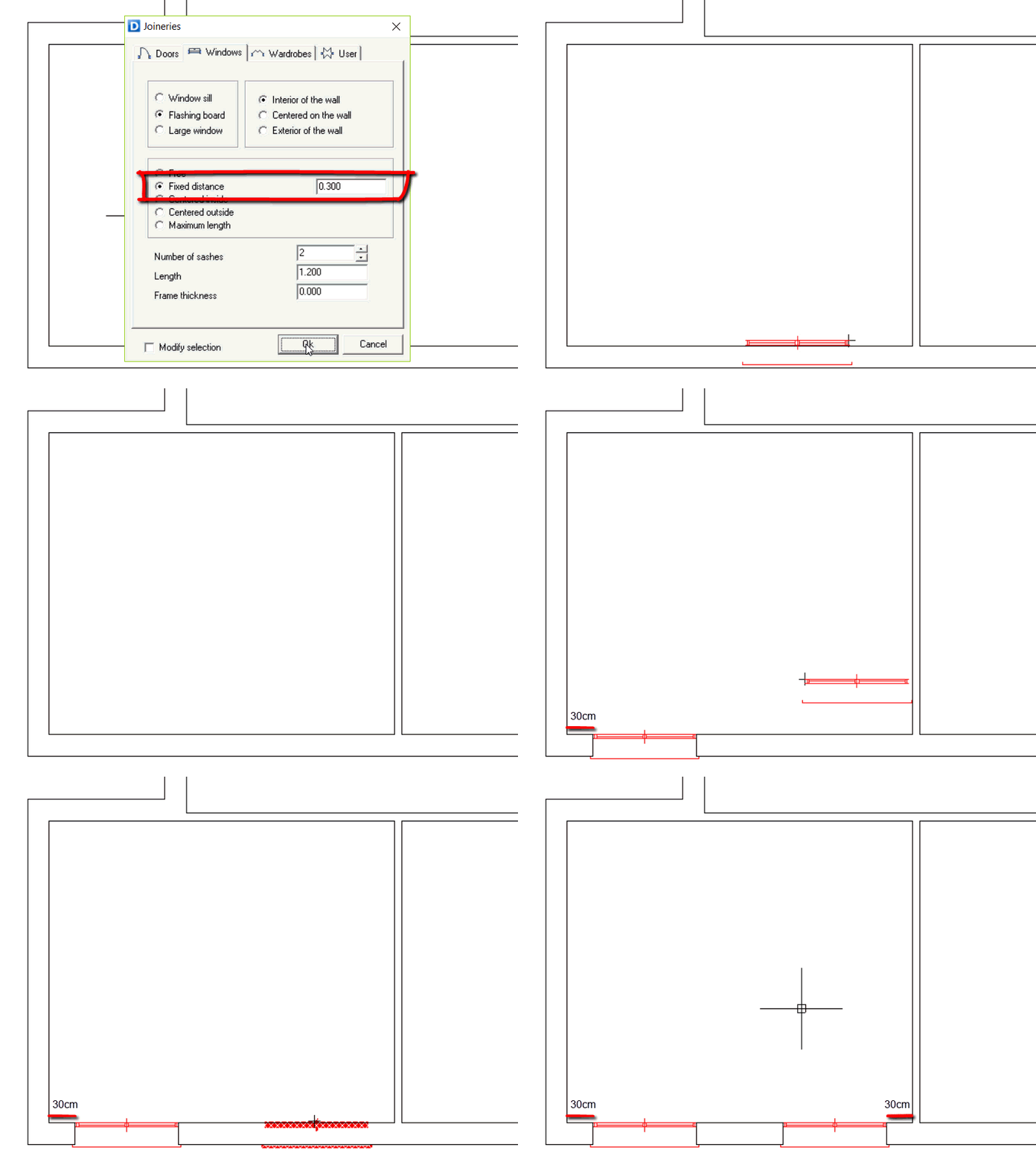
[FREE]. The “Free” option allows us to place a window on any part of the partition. The window is displayed before being placed. When it is being displayed, if you want to change the insertion point origin before placing it, click on an empty space.
-
[FIXED DISTANCE]. When you select this option, a box appears to the right of the window, where you can type a distance (in meters). This option allows you to place one side of the window at a specific distance from the corner closest to it. Then the window is drawn.
-
[CENTERED INSIDE]. With the “Centered Inside” option, the window will be drawn centered with respect to the partition line that you marked to indicate the opening direction of the window.
-
[CENTERED OUTSIDE]. With the “Centered outside” option, the window will be drawn centered with respect to the other line that makes up the partition, which is different from the one you marked to indicate the opening direction of the window.
-
[MAXIMUM LENGTH]. The “Maximum length” option will draw the largest window that can fit on the wall.
4. Windows measurements and their opening angles
-
[Number of sashes]. Indicate the number of sashes of the window.
-
[Length]. The total window length is indicated in this box.
-
[Frame thickness]. This option refers to the frame dimension perpendicular to the wall. In this box, you will be able to define the frame thickness in meters. Ex.: 0.05 m. = 5 cm
3.5.3.Wardrobes
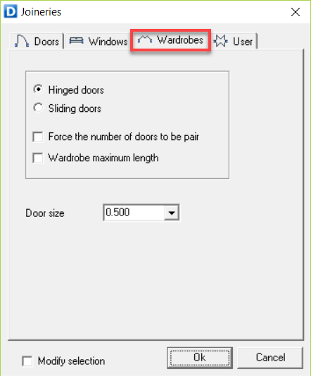
The dialogue box that appears indicates the panel measurements. The program has a panel measurement of 30 cm to 80 cm by default, increasing by 10cm lengths. However, you can enter any size.
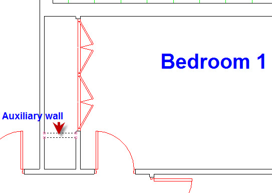
The wardrobe can be with sliding or hinged doors. If the wardrobe does not fit in the partition, it will not be drawn.
You can select the number of doors to be an even number. This is especially useful in wardrobes with sliding panels.
To change the insertion point of the wardrobe, click on an empty space when the wardrobe is displayed.
3.5.4.Modify joineries
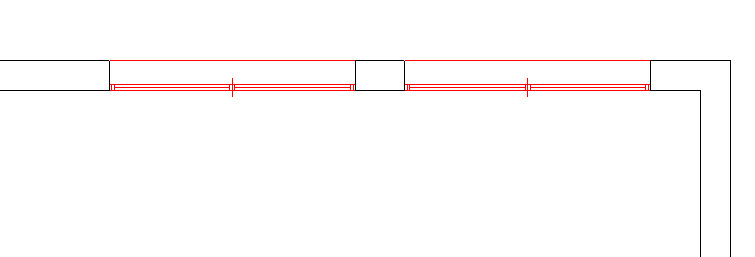
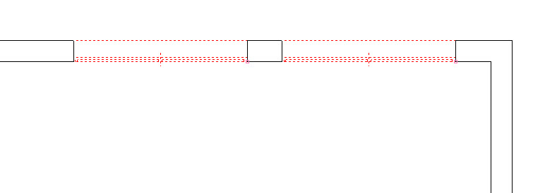
This allows you to modify doors and windows, as long as they have the same total length including the frame.
It also allows you to modify wardrobes, but only if they have two doors, as the only possible modification is to change the type of door (sliding or hinged).
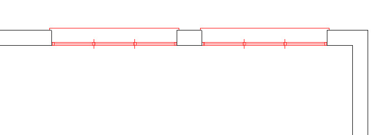
EXAMPLE
3.6.Pillars
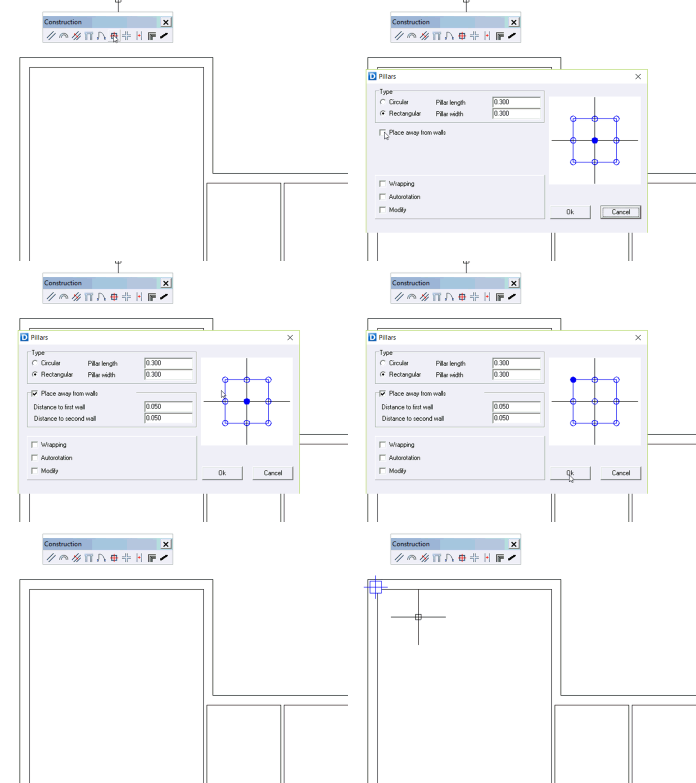
With this function, you can place rectangular or circular pillars of any dimension in the drawing. You can also edit the settings of the pillars (basepoint, dimensions and location) in the dialogue window that opens after clicking on the tool.
In the pillars menu you will be able to create new pillars or modify existing ones.
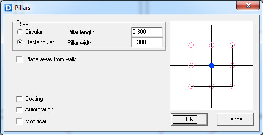
PILLARS MENU
You have 4 sections in the pillars menu:
 Type
Type
In this section you can choose the type of pillar to be either circular or rectangular. If you choose a rectangular pillar you will have to specify its dimensions (length and width). If you choose a circular pillar you will have to specify its diameter.
 Place away from walls
If you enable this function the pillar will be placed at a certain distance from two walls (this function does not work with lines). Once the box its checked you can specify the distances from the respective walls and after the settings are confirmed you would need to click on one of the external sides of the walls to place the pillar.
If you do not activate the [Place away from walls] option, you may approximate and place the pillars freely on any item in the drawing, like straight lines, wall corners, guides, etc.
 Basepoints
The basepoints are the corners, center and midpoints of the pillar. These points snap with other objects such as lines and walls to facilitate the insertion.
After the settings are confirmed, the basepoint will specify the insertion point of the pillar. The pillar can be rotated using:
-

 (SHIFT+ Left click) rotates 90 degrees with each click
 -

 (CONTROL + Left click): rotates 45 degrees with each click.
 Options
-
Wrapping. If this option is checked, the program will create a wrapping around the pillar when it is placed in the walls. You can specify the thickness of the wrapping.
-
Autorrotation. If this option is enabled, the pillar will rotate during the insertion when it snaps to a wall. The position of the rotation will depend on the selected basepoint and the direction of the side of the wall.
-
Modify. This option will modify an existing pillar to add the wrapping if it didn’t have it. This option does not work to modify the dimensions of an existing pillar. In this case you would need to delete it and insert a new pillar.
EXAMPLE / PRACTICE
This is an example of the location of pillars on the floor-plan drawing:
Select pillar function.
- Rectangular 0.30×0.30
- Set the basepoint at the top left.
- Check “Place away from walls”
- [Distance from walls] 0.06
- [Accept]
A cursor appears on the screen with the preview of the defined pillar.
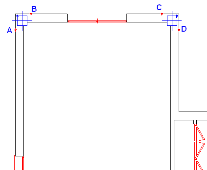
Click on the first outer line of the wall (A) and then on the second outer line of wall (B).
The pillar should now be placed at 6 cm from the indicated walls.
Now, turn the pillar until the cursor is in the top right-hand corner, by pressing the following: SHIFT + LEFT CLICK
Click on the first outer wall of the facade (C) and then on the second (D).
Proceed like this with the rest of the corner pillars.
Next, in the guide’s toolbar, select the icon:
[Guide Intersection]
Click the center of pillar 1 and then on the center of pillar 2.
Two guides are drawn at each intersection of the two indicated pillars. When using pillars to create guides, the symbols include 9 points corresponding to the pillar center, sides and corners.
Click again on the pillar function:
- Deactivate [Place away from walls]
- Type: Rectangular, 0.30 x 0.30
- Basepoint: center.
- [OK]
Place the pillar on the corresponding point of the guide.
Repeat this process for the rest of the pillars until all of them are placed.
Click again on the pillar function:
- Deactivate [Place away from walls]
- Type: Rectangular, 0.30 x 0.30
- Basepoint: center.
- [OK]
Place the pillar on the corresponding point of the guide.
Repeat this process for the rest of the pillars until all of them are placed.
Although you can insert the pillars with their wrapping, it is not a good idea to do this until you are sure that the pillars are definitively arranged in place
Once the pillars are placed, if you want to modify them to apply a wrapping:
Click on the pillar function again.
- Activate: [Wrapping] (0.05 m).
- Activate [Modify].
- [OK]
With the cursor that appears, select individually (or use a selection box) the pillars that you want to modify and then confirm it by right clicking
Finally, to erase the guides, enter:
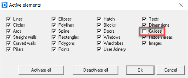
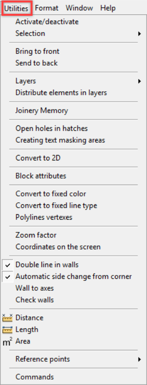
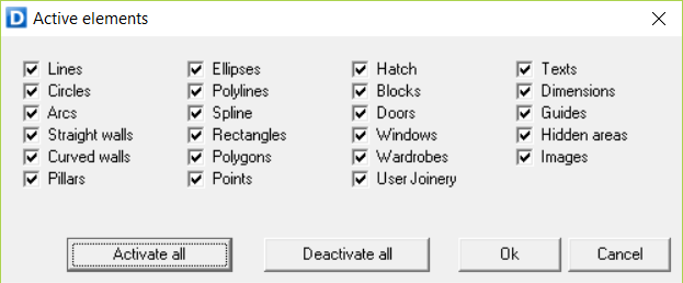
[Utilities] – [Activate/Deactivate]
[Deactivate all] and then just activate [Guides]
[Ok]
Only the marks will remain visible, making them easier to delete by creating a selection window and pressing the DELETE key
Lastly, return to [Utilities] – [Activate/Deactivate] – [Activate all].
[Accept].
The complete drawing appears without any marks.
Finally, save this drawing again as LEVEL 0
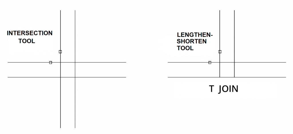
3.7.Intersection
Consequently, it is not recommended to fix a “T” junction with the intersection tool. If so the program will create an overlap of small walls. Furthermore, the junction of the walls may create errors that will cause problems when calculating areas or creating hatches.
3.8.Lines to walls
With this tool, you can convert two simple straight lines, whether parallel or not, into walls.
This way you will be able to insert joinery items into these walls created from two straight lines.
Click on the tool and select the lines you want to convert into a wall. They will be automatically converted into a wall.
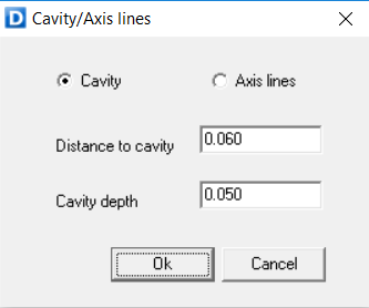
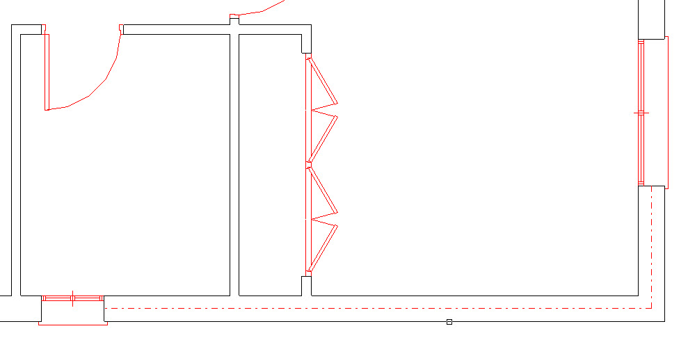
3.9.Cavity and axis lines
3.10.Staircase in elevation view
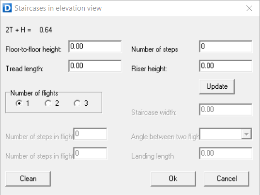
This tool draws the whole elevation view of a staircase that can enclose up to three flights of stairs per floor level.
You will find this tool in the Construction toolbar, or you can select the option [Staircase] in the flyout menu of the tab [Construction].
First, you must indicate the floor-to-floor height. Then, you can type the number of steps that comprise the staircase. The riser height and tread/run length will all be calculated automatically using the formula:
2 x riser height + tread length = 0.64
One flight
Depending on the value you set as [Floor-to-floor height], [Number of steps], [Tread length] and [Riser height]), the values in the other entries will be affected according to the following criteria:
-
[Number of steps]. When you change the value in this entry, both riser height and tread length will be recalculated.
-
[Riser height]. A change in the riser height will affect the height between floors and tread length.
-
[Tread lenght]. Modifying this value will modify the value of the formula (2 x riser height + tread length) mentioned previously.
When you change one of the previous settings, you can always update the changes in the other entries by clicking on any of them or by clicking on the [Update] button.
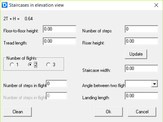
If the staircase has more than one flight (up to three) per level you must indicate this in the corresponding option [Number of flights].
Two flights
If there are two flights, you will see the following items activated.
-
[Stair width]. This value is needed to draw the flights facing forward.
-
[Number of steps in flight 1]. In this entry you define how many steps the first flight has. If you type zero, the program will use half of the steps for each flight.
-
[Angle between flights]. Indicates whether the second flight forms a 0º, 90º or 180º angle with respect to the first flight.
-
[Intermidiate landing length]. In this entry you can indicate the length of the intermediate landing. If you indicate zero, the program will use 1.00 meter.
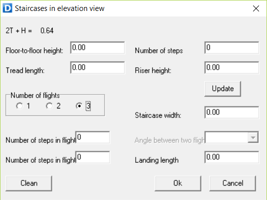
Three flights
If you specify three flights:
-
[Angle between flights]. You´ll see that this is deactivated, as each flight will be at 90º with respect to the next one.
-
[Number of steps in flight 2]. This one is activated. If its value is zero, the program will use half of the remaining steps, not taking into account those in the first flight. If that value is also zero, half of all steps will be used.
4.Draw Toolbar
4.1.Line
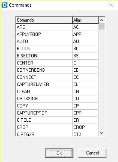
Commands: “LINE”, “LI”

This function allows you to draw simple straight lines.
You can start by clicking on any point and finish the line in the same way. If you do not escape the function, you can keep on drawing consecutive lines.
-
If the ortho mode is enabled, the lines are drawn perpendicular to each other.
-
With the ortho mode disabled, the lines can be drawn freely.
To start at a different point, right click twice, this way you exit and restart the function again.
To draw a straight line with a defined length, click on-screen to determine de starting point, afterwards indicate a direction, type the distance and press Enter.
4.2.Polyline
Commands: [POLYLINE], ‘PL’
With this function, you can draw a single object that is composed of line and arc segments.


The polyline will close automatically by pressing C + Right click. It will also close automatically when clicking on the starting point of the polyline.


To change from straight line to arc, use A + Right click; and use R + Right click to return to a straight line.


While drawing the polyline, every time you press the CTRL + Z keys you will be able to remove the last specified point.
4.3.Spline
Commands: ‘CP’
This function allows you to draw a sequence of tangential arcs indicating points.


Press CTRL + Z to delete the previous arc. You can do this as many times as the number of arcs created
After creating the last point, right click 4 times to start a new curve.


If you want to close the spline automatically, type C and press ENTER.
4.4.Circles
Commands: “CIRCLE”, “CR”

This function allows you to draw circles.
We can use 4 methods to draw circles: RADIUS, DIAMETER, 3 POINTS AND TANGENT TO 3 STRAIGHT LINES
-
[Radius]. Type R + [Enter]. This is the default method. You will be able to draw a circle by specifying its center and typing the value of the radius + Enter, or by specifying the endpoint of the radius.
-
[Diameter]. Type 2P + [Enter]. This method draws a circle based on two endpoints of the diameter. Just click on the first point and then on the opposite point of the diameter and the circle will be drawn automatically.
-
[3 Points]. Press 3P + [Enter]. This method created a circle tangent to three points. For this just click on three points of the drawing
-
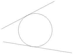
[Tangent to straight lines]. Type 3T + [Enter]. With this method, you draw a circle that is tangent to three straight lines. Just select these three lines.
4.5.Arcs
Commands: “ARC”, “AC”
With this function you will be able to draw arcs defined by three points or defined by their central radius and initial and final angles.
-
[Three points]. Specify the three points on the arc´s circumference.
-
[Angle]. In this case, the center of the circle should be selected first, then the value of the radius can be entered numerically or by clicking on screen. Next, the initial angle should be specified and subsequently, the final angle. Both included angles can be indicated either numerically in degrees or by moving the pointing device and clicking.
To change from one modality to another, use P + right click to change to three points and R + right click to change to the angles method.
4.6.Ellipse
Commands: “ELLIPSE”, “EL”
With this function you will be able to draw ellipses. With this function you will be able to create an ellipse or an elliptical arc.
 First, specify the center of the ellipse by clicking on screen
 Next, the cursor should be moved to indicate the direction and length of the major axis. You can determine the length of this axis by specifying the endpoint or by typing its length
 Finally, move the cursor up or down to set the length of the major axis or type the length of this axis to create the ellipse.
To draw another ellipse, double-right click to restart the function
4.7.Point
Commands: “POINT”, “PT”
This function creates a point object. You can place points on the drawing represented by a symbol.
These points are differentiated from guides, as their shape can be modified and they belong to the drawing not to the grid pattern. Consequently, they will be visible when printed.
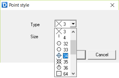
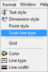
You can customize how these points are displayed. Select the option [Point style] in the flyout menu of the tab [Format].
When you select this option, a point style dialog box opens. The following options are displayed:
Style: specifies the image used to display point objects. Size: Sets the point display size.
4.8.Rectangle
4.9.Polygon
Commands: “POLYGON”, “PO”
This function allows you to create an equilateral closed polyline. These closed polylines behave as an object. They can thus be selected and/or deleted by clicking on one of their sides.
When you launch this command, a dialogue box opens. There you can define:
-
[Number of sides]. Specifies the number of sides in the polygon
-
[Autorotation]. If this option is activated, you will be able to determine the rotation angle of the polygon on-screen when it detects a line, wall or arc with a specific direction.
-
[Side] or [Radius]. You will be able to choose between setting the dimension of the circumscribed radius or one of the sides of the polygon.
-
[Dimension 1]. This value specifies the length of the side or the circumscribed radius of the polygon.
-
[Dimension 2]. This option is only editable when the polygon has 4 sides
4.10.Bisector
4.11.Tangents
4.12.Insert block
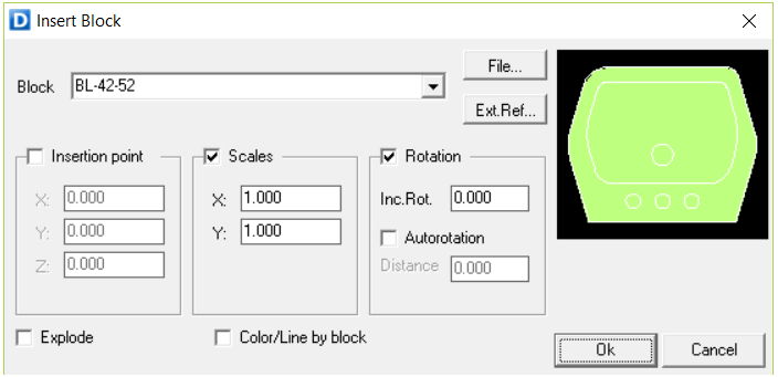
You can use this function to insert a block or drawing into the current drawing. When you activate the insert block tool, a dialog window pops up. In the opening dialog window, you will be able to browse any block from the library of Dibac or from any other path
To do this click on the [File] button and select the desired object.
A preview of the selected block will be displayed in the window on the right side.
You can define the following settings:
-
[Insertion point]: Specifies a location for the block on the drawing. You can define this location on-screen or by typing the coordinates.
-
[Scales]: All X and Y dimensions of the block or drawing are multiplied by the X and Y scale factors.
-
[Rotation]: You can determine the angle of rotation for the block.
-
[Autorotation]: This option is used to align the block automatically with the walls or partitions of the drawing.
-
[Distance]: Likewise, you can define how far away the block will be placed from the selected wall in the drawing. This distance is always considered in a direction perpendicular to its rotation.
-
[Explode]: If this option is selected, when you insert the block it will automatically be broken into its component objects (lines and arcs).
By clicking on the button Ok, you will confirm the settings and the block will appear on-screen to be placed in the drawing.
Shortcuts to rotate a block:
-

 Increase of 90º
 -

 Increase of 45º
 -
AUTO ORIENTATION. Place the block on the line and press

4.13.Create block
Create a block
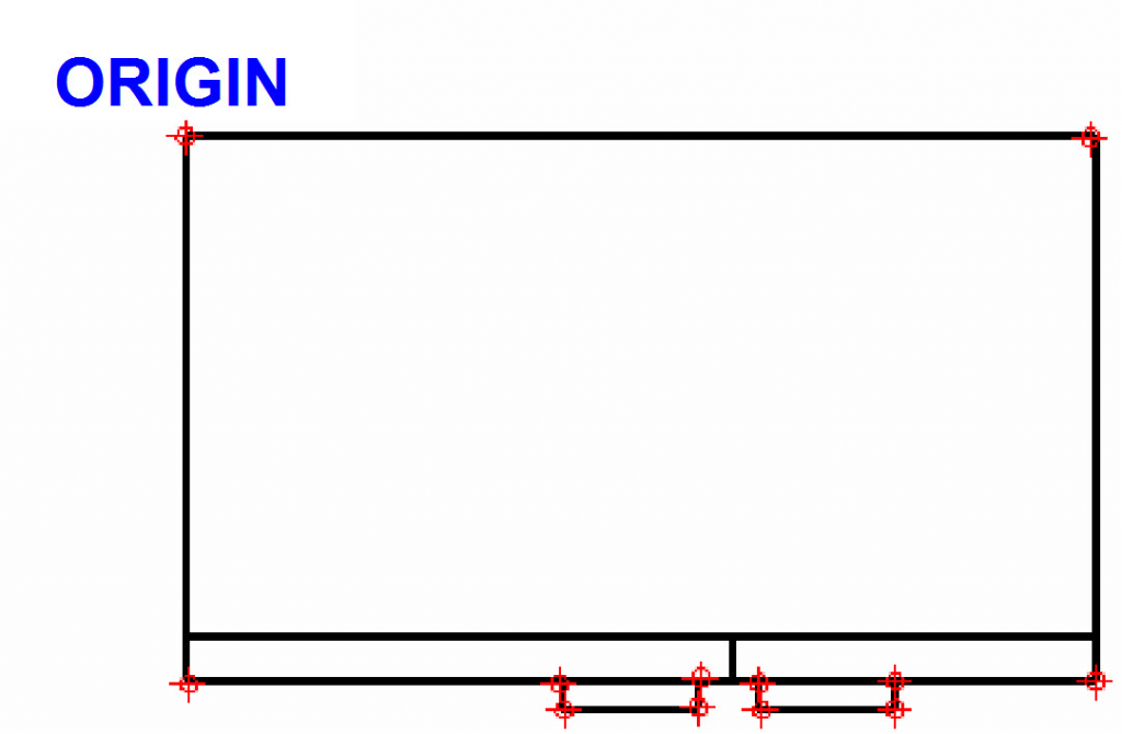
We are going to create a fridge block as an example. We will include a deletion area in the fridge to hide whatever might be underneath the block.
 Draw the fridge.
First, you must draw a plan view of the fridge. The drawing will have a similar aspect to the adjoining figure.
You need to create a deletion area to hide the objects within the perimeter of the fridge. To create the deletion area, provide a SOLID HATCH (by default 71) to the surface of the fridge.
With the HATCH function active, use the point-by-point option to select the perimeter for the hidden area.
 Convert the drawing into a block.
Once we have the drawing of the fridge, we are going to convert it into a block.
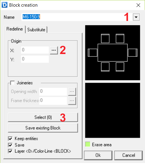
Select the function: [Create Block]
The block definition dialogue box appears. Do as follows:
3. Click on [Select]. This option will return to the drawing. Select the geometry of the fridge with a selection box and confirm with a right click. You will return to the block dialogue box.
4. Check that the [Erase Area] matches with the geometry.
5. Click [Accept].
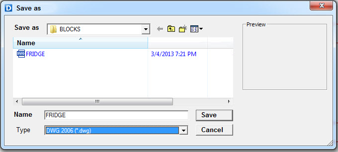
 Save the block.
After clicking Ok, another dialog window pops up, where you can save the block created in the directory.
The block (object) defined this way is now available to use in any drawing.
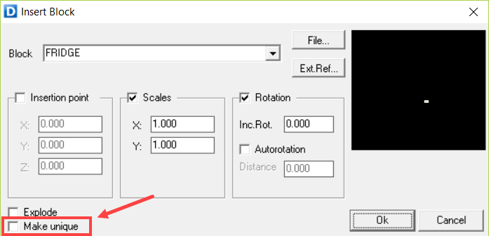
Make a unique block
This function allows to make a unique block of an existing block.
It is used when you want to edit a block but you want all the existing copies of the block to retain the previous definition and attributes.
To do this double left click on the block you want to make unique.
Select the “MAKE UNIQUE” checkbox and click on the [Ok] button.
By making the instance unique, you are creating a new component based on your original.
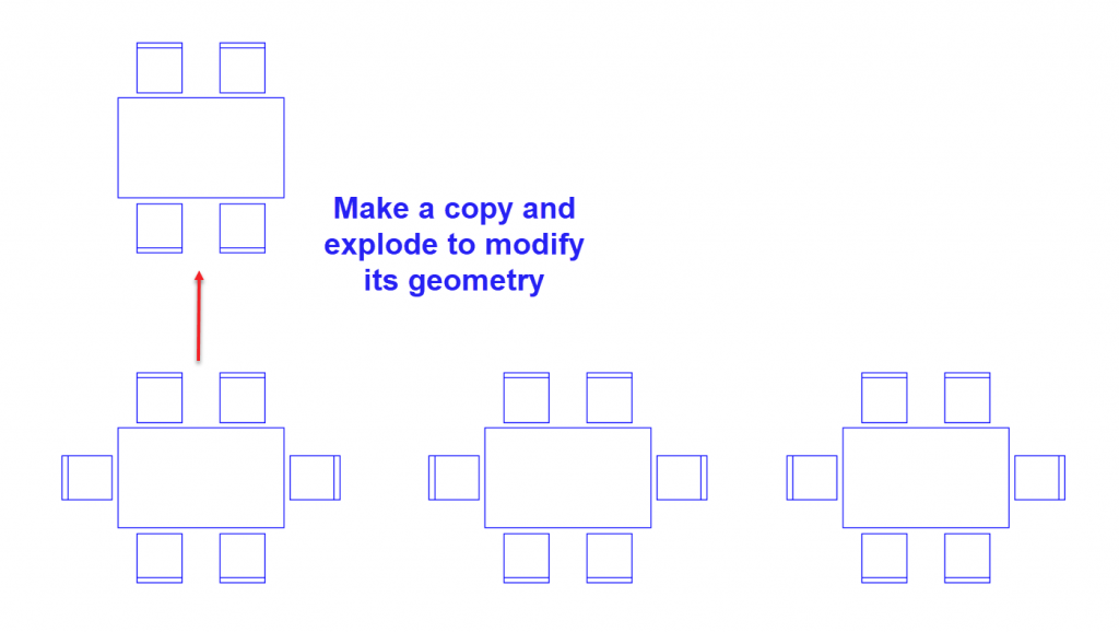
Modifying blocks
The function CREATE / EDIT BLOCK allows any block inserted into the current drawing to be modified.
Select the block you want to modify.
Make a COPY of the block and EXPLODE it.
Modify the geometry of the exploded copy.
Once the modification is completed, click on CREATE / EDIT BLOCK.
A dialogue box pops up. Do as follows:
-
Select the block from the Name drop-down list of block definitions in the current drawing.
-
Click on the […] button in the Base point section. Specify the same base point as in the original block.
-
Click on the [Select] button to specify the objects on-screen.
Return to the drawing and make a selection box around the modified geometry.
Confirm it with a right click 
You will return again to the block definition dialogue box.
Click on the [OK] button to save the changes.
Click on the [CANCEL] button to exit this window without saving the changes.
The following message will be displayed: “The drawing has not been saved”. Click [Accept].
To modify a distorted block in X or Y, it’s necessary to explode it first and make it unique using the [CREATE BLOCK] tool.
A scaled block in proportion X=Y (scale uniformly), can be modified directly.
4.14.Distribute
Command: “DI”
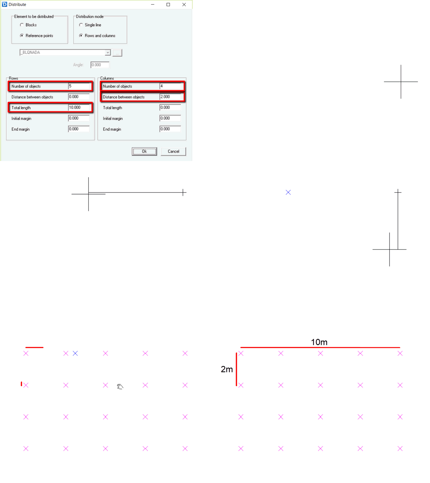
Use this function to evenly space blocks or reference guide points in rows and columns inside a delimited area.
You can choose between:
Distribute Blocks or Reference guide points in one row or in rows and columns.
When the option “Block” is selected, you can distribute a block from the drawing or space a block from the library.
You can also define the rotation Angle for placing the blocks.
Once the object has been selected and it has been decided whether to distribute it in one row or in rows and columns, the spacing criteria should be set.
You can choose several methods:
-
Specifying the total number of items and the distance between them. By following this method, you will ignore the total length.
-
Specifying the distance between items. The items will be spaced in the direction within the indicated line
-
Specifying the total length and the number of items. The distance between items will be calculated automatically.
After specifying the distribution values, press [Ok] and click on the viewport to specify the starting point of the distribution.
Afterwards, move the cursor to define the direction of the rows (for example, horizontal) and click again.
Move again the cursor, also from the origin, to specify the second direction for the columns (for example, vertical) and click once again.
The defined distribution will display on screen.
4.15.Hatch
With this function, you will be able to fill either an enclosed area or a perimeter made up of points with a hatch pattern, solid fill or gradient fill.
When the function is activated, the hatch dialogue box pops up. In this window, the following prompts are displayed:
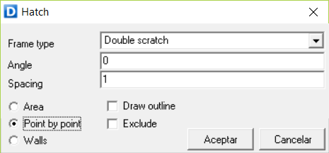
-
[Type]
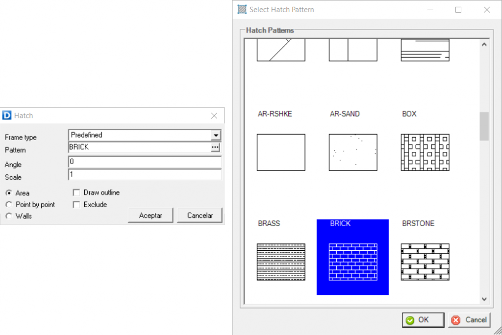
There are several types of hatch in the drop-down list: [Predefined], [Single scratch], [Double scratch], [Image], etc.
Depending on the type selected, the parameter fields defined below change.
-
[Pattern]
When the [PREDEFINED] hatch option is selected, the [PATTERN] parameter is activated.
By selecting this option from the drop-down list, a window appears with the predefined hatching patterns. You can select any of them.
-
[Angle]
Specifies the angle of the hatch pattern
-
[Scale]
Increases or decreases the pattern size.
-
[Spacing]
When the pattern selected is a single or double scratch, a window appears in which you can define the spacing of the hatch lines in meters.
-
[Draw outline]
Draws a contour line along the perimeter of the area of the hatch.
-
[Enclosed area]
With the Enclosed Area option, the hatch or solid fill is inserted inside an enclosed area by clicking on one of the lines of the wall or partition, whether it has doors, windows, wardrobes or holes in the partitions.
This option allows to create hatches within enclosed areas made up of lines, arcs, circles, polygons, etc…
-
[Point by point]
The Point by Point option draws a pattern or solid fill inside a perimeter made up of consecutively introduced points. This way you indicate the boundaries of the hatch. Once the boundary is completed click again on the first point and then right click to finalize.
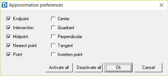
It is a good idea to have the [Endpoint] option activated in the object snap settings to specify precise locations on objects in the drawing without manually pinpointing them.
To edit the properties of an existing hatch, left-click twice.
To leave a hole within the hatch of an enclosed area, select all the perimeter boundary points and then the boundary points of the hole in the opposite direction that is starting with the closest boundary point of the hole to the last boundary point selected in the perimeter. Once the hole has been defined, return to the last boundary point selected in the outer perimeter to complete the command.
-
[Exclude]
Another option available is the Exclude option, with which you can remove any area from a hatch by using the “Point-to-Point” or “Closed area” systems. This option opens a permanent space in the hatch. On most occasions, it would be preferable to use a Block with a “deletion area,” which only hides the hatching below.
4.16.Text

This function allows you to create texts and insert them into the current drawing
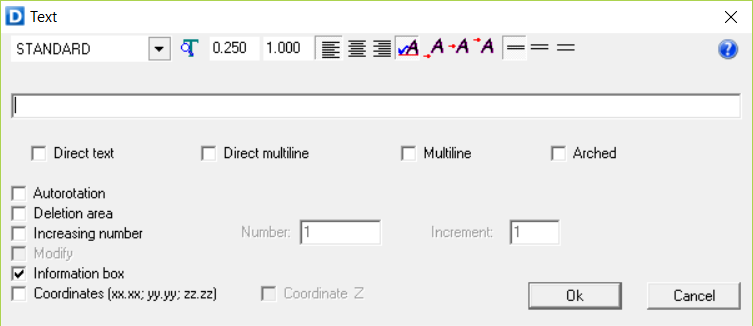
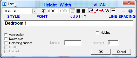
When you select this function, the text formatting dialog box opens.
4.16.1.Style and font
The first tab shows the name of the current text style (STANDARD by default). Clicking on the drop-down list box on the tab displays all of the previously defined text styles.
Defining a new style
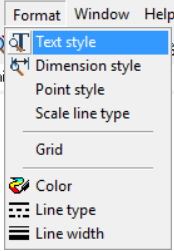
A text style is a named collection of text settings that controls the appearance of text, such as font, line spacing, justification, and color. To define a new text style, click on the icon next to the tabbed dialog box text style.
Another new window appears: [Text Style].
For example, type the name [PERSONAL STYLE] in the dialogue box title. Afterwards, click the [OK] button.
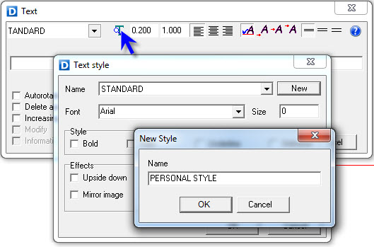
Select the font type and the style of font (Bold, Italics and Underlined) for this new text style.
The text style dialog window also allows to change the font size and create some basic text effects.
When completely defined the new text style, press the [OK] button and you will return to the text formatting dialog box.
You can save this and every created text style in the current project by saving the template of the drawing. To do this, save the file and then you can assign a new template in Tools > Preferences > General > Template for new drawings. Locate the saved template to assign it.
Next time you open Dibac CAD the created text and dimension styles of the template will be enabled and ready to use.
Settings
In the text formatting dialog box are other task tabs and options, as follows.

-
[Height]. Refers to the height of the text.
-
[Width]. Refers to the width of the text.
-
[Horizontal alignment]. This setting determines how the text is displayed horizontally on the page. The types of text alignment include left aligned, right aligned and centered.
-
[Vertical alignment]. Aligns the text vertically, from the bottom, the center or the top.
-
[Line spacing]. Changes the separation between lines of text. If you place text on top of another text, the latter will be positioned below the former, at a distance equal to the chosen line separation.
In the horizontal text box, you can type the text you want to insert in the current drawing.
4.16.2.Direct text
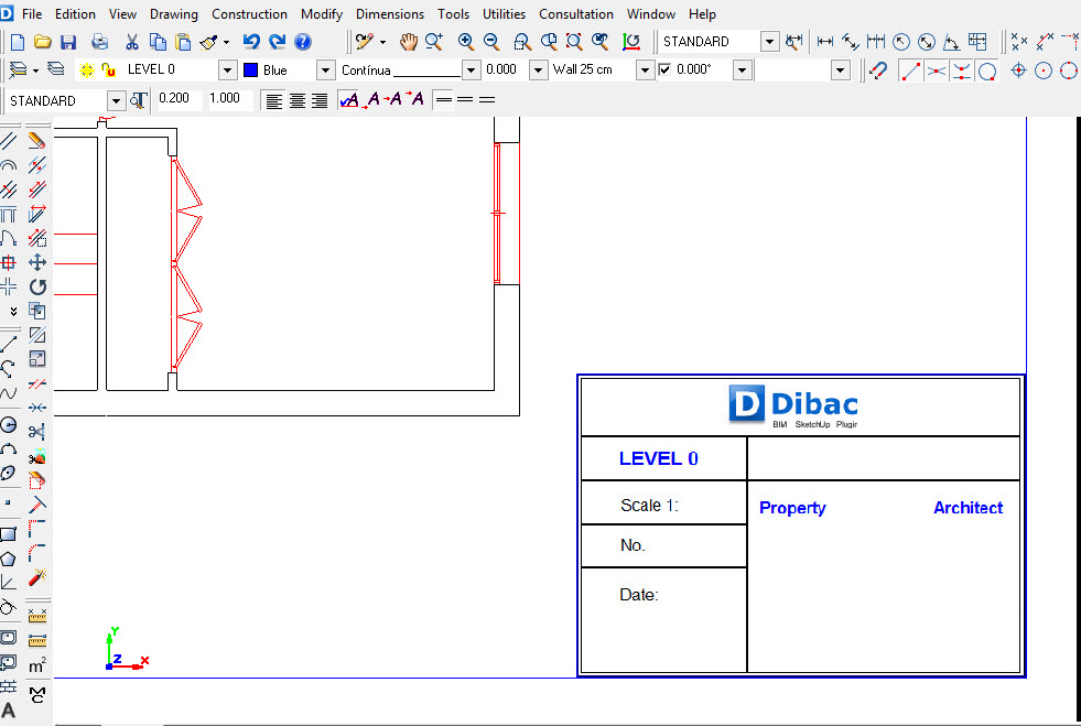
When activating this option, it is possible to write text lines directly on-screen. You should have selected a text style beforehand.
 First, by clicking, specify the insertion point for the first text character.
 A cursor will appear to type a text line. While writing you can correct the typed characters by clicking on any part of the written text or moving the cursor using the keyword arrows.
 When you are done, right click or press the [Intro] key.
Once the first line of the text is completed, you can continue typing a new text line in any position. To exit the function, right click or press [Esc] before inserting a new text line.
4.16.3.Direct multiline
The “Direct Multiline” option is similar to the previous Single-line DIRECT TEXT option. Except that instead of finishing the text when pressing [Enter], you will go on to the following line to keep writing.
4.16.4.Multiline
When selecting the “Multiline” option, a window with a text box opens. In this text box you can type a text with several lines. These lines will be placed in the drawing inside a bounding box which defines the width of the multiline text object.
The dimensions of the bounding box will be defined on-screen with two clicks specifying opposite corners.
The written text will follow the height, font type and size, lines spacing and alignment which have been defined in the text formatting dialog box.
In the File menu, click “Open” to load the content of any text file.
The option “Clean” of this menu will delete all the written text in the window.
4.16.5.Curved text
Select the “Curved text” option from the text formatting dialog box to create a text that aligns, or bends, along a previously drawn curve.
Once the text is typed, select the “Curved text” checkbox, press the OK button and select a curve in the drawing.
This function does not work with the Spline command, only with the Arc command.
4.16.6.Autorotation
If the checkbox of this option is activated, the text will automatically be oriented towards the direction of the detected lines.
4.16.7.Deletion area
If the checkbox of this option is activated, a solid fill will be created in the drawing under the text to make it more legible. For example, if the text is placed over a hatch, the deletion area option should be activated so that the hatch does not interfere with the text object.
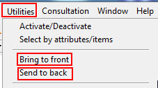
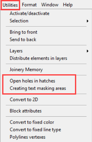
If you insert the text object with the option [Deletion area] activated and you want to see the objects below the text, select the text object and click on the command [Send to back] in the Utilities menu of the context toolbar.
These solid fill “Hidden areas” can be activated or deactivated using the [Activate/Deactivate] command in the [Utilities] menu of the context toolbar.
4.16.8.Create text hidden areas
This is a command in the [Utilities] menu.
This command automatically creates a solid fill “Hidden area” in all the visible text objects on the current layers to hide any object below the text.
4.16.9.Open holes in hatch
This command is in the [Utilities] menu.
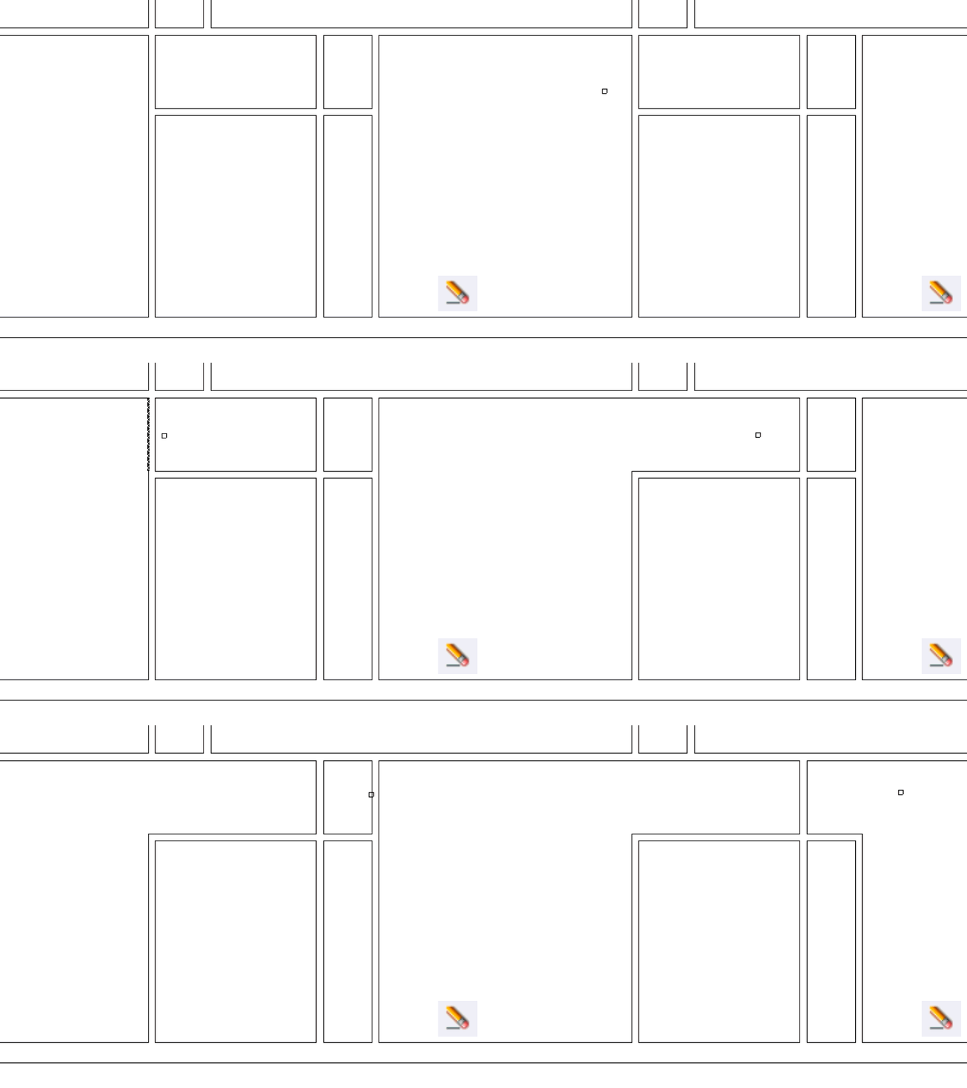
This function opens holes in any hatch that has a text object or a selected block with a “deletion area”.
If the objects were selected before using the command, the holes will be opened in the selected blocks and text objects that interfere with any hatch. Otherwise, the selection cursor will appear so that the blocks can be selected in the drawing.
As the hatch is permanently broken, this option is useful in exporting the drawing to other programs which do not have the Dibac solid fill function for masking objects.
The advantage of masking objects with a solid fill and not breaking the hatch is that the text objects or blocks can be deleted or moved freely, while maintaining the solid fill area.
4.16.10.Sequentially number
You can insert text objects with a numerical value that increases every time you place a new text object. To do this follow these steps:
 In the text formatting dialog box, enter two consecutive percentage symbols (%%) after the text. These symbols will be replaced by the increasing number.
For example, type “Plot Number %%”.
 Then, activate the [sequentially number] checkbox option from the text formatting dialog box and enter the starting number in the [Number] text box and the increment in the [Increment] text box.
In case of an erroneous placement, press Ctrl + Z to delete it and the sequence will automatically subtract one increment. 

4.16.11.Information box
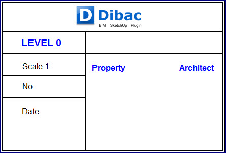
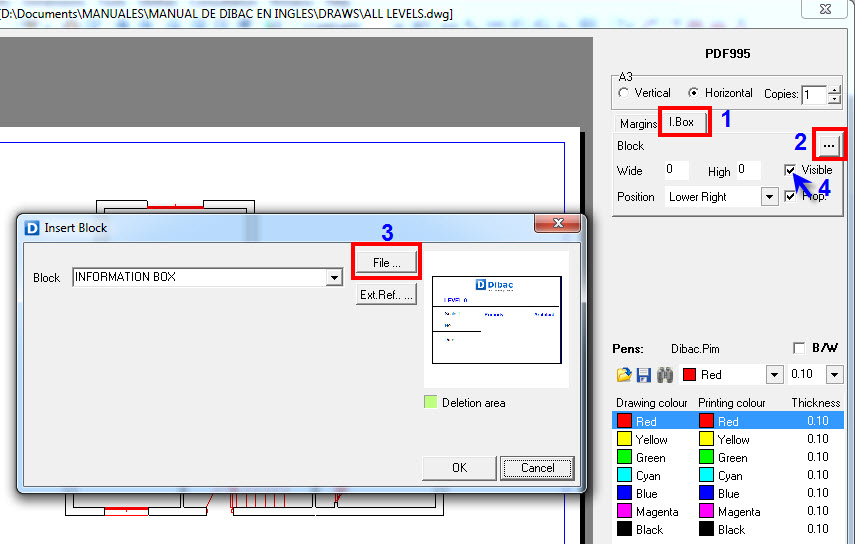
The [Information Box] option in the text formatting dialog box allows you to associate texts to the selected information box when you are placing texts in a layout.
Once these texts are associated, they can be moved or rescaled altogether if you modify the position of the information box under [Page Setup/Print].
4.16.12.Coordinates
Use this option to create and place a text object with the coordinates of a specific point.
There are two ways of implementing this function::
1. Typing the coordinates in the text box with the following format:
The first way is to write the required coordinate in the text window with the following format:
X, Y and optionally, Z
Decimals must be written using a point.
For example, coordinate X=10.25 Y=14.32 will be indicated as following: 10.25;14.32
Check the [Coordinates (xx.xx;yy.yy;zz,zz)] box.
Click [Accept] or press INTRO and close the text formatting window. The text object with the coordinate will be placed at the point that corresponds to that coordinate.
2. Leaving and empty text window
The second way is by leaving an empty text window and clicking [Accept]
The cursor to start clicking on the desired points will appear.
Every time that you click an exact point, the label with its coordinates will be displayed.
This label can be moved, so it can be located wherever you want.
With both methods, if you have accepted the option “Coordinate Z”, the text with the coordinates will include the latter.
4.16.13.Special characters
To write special characters not included on the keyboard, hold the ALT key and type the corresponding number code. When you release the ALT key, the symbol will appear in the text space.
Most-used characters and their codes.

Click [Accept]. Next, the rectangle containing the text should be movable. The circle at its origin will act as the cursor, with all its characteristics regarding rotation, scale changes, etc.
 To place the text, just click
 To enter different text, right click.
4.16.14.Text search
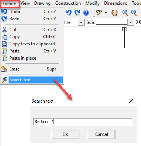
This function allows you to search any text located in any part of the drawing.
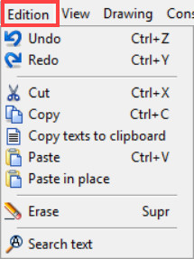
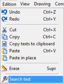
To search for a text: [EDIT] / [SEARCH TEXT].
A window appears in which you can enter the text that you want to find.
Once the text is found, it remains centered on the screen.
If there are several equal text boxes, but in different locations, press the “S” key to jump to the next one.
This can be very useful. For example, when looking for the name of a plotting sheet, or just a type of enclosure, etc.
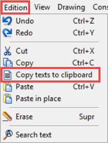
4.16.15.Copy text to clipboard
4.17.Images
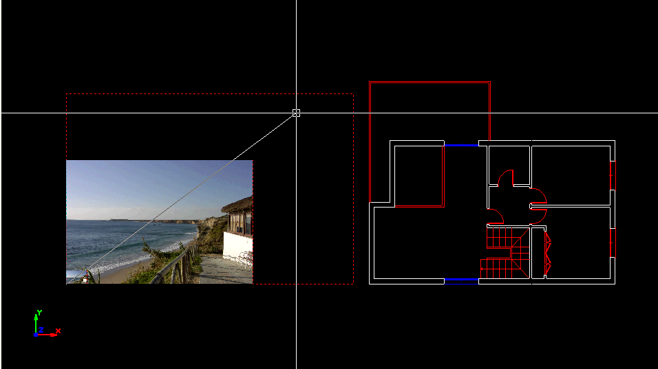
When you click on this option, a browser window opens in which you can select the image you want to insert into the drawing.
Specify with one click the insertion point and then move the cursor to determine the size of the image with another click.
When printing on white paper, you can crop the image with any polygon.
The procedure is as follows:
 Draw the polygon on the photo, with a different color than the background.
 Fill this polygon with a solid color hatch (the same color as the polygon).
 Select the image and, in the [Utilities] menu, select [Send to back].
 On the print screen, change the polygon color to white paper (which is the color of the paper).
5.1.Erase and Delete
With this function, you can delete any item. To do this, left click on the item and confirm with a right click.
You can also create a box that will delete everything inside or in contact with the box.
After selecting the erase function, click once and drag the cursor from left to right clicking on the opposite vertex. This way you can delete all the items completely inside the box after doing a right click.
If you drag the cursor from right to left, all items inside or in contact with the box will be deleted. In the case of texts, blocks or polygons, the origin of the item will be deleted.
When the function is not being used, it can be activated pressing the DELETE key.
With this function, you can also erase any previously selected item.
To do this, first select the items to be deleted, individually or using a selection box with the cursor.
Then press the [DEL] key or click on the [Erase] icon.
To mend the rest of the walls and partitions of the drawing when deleting others, they must be erased one by one.
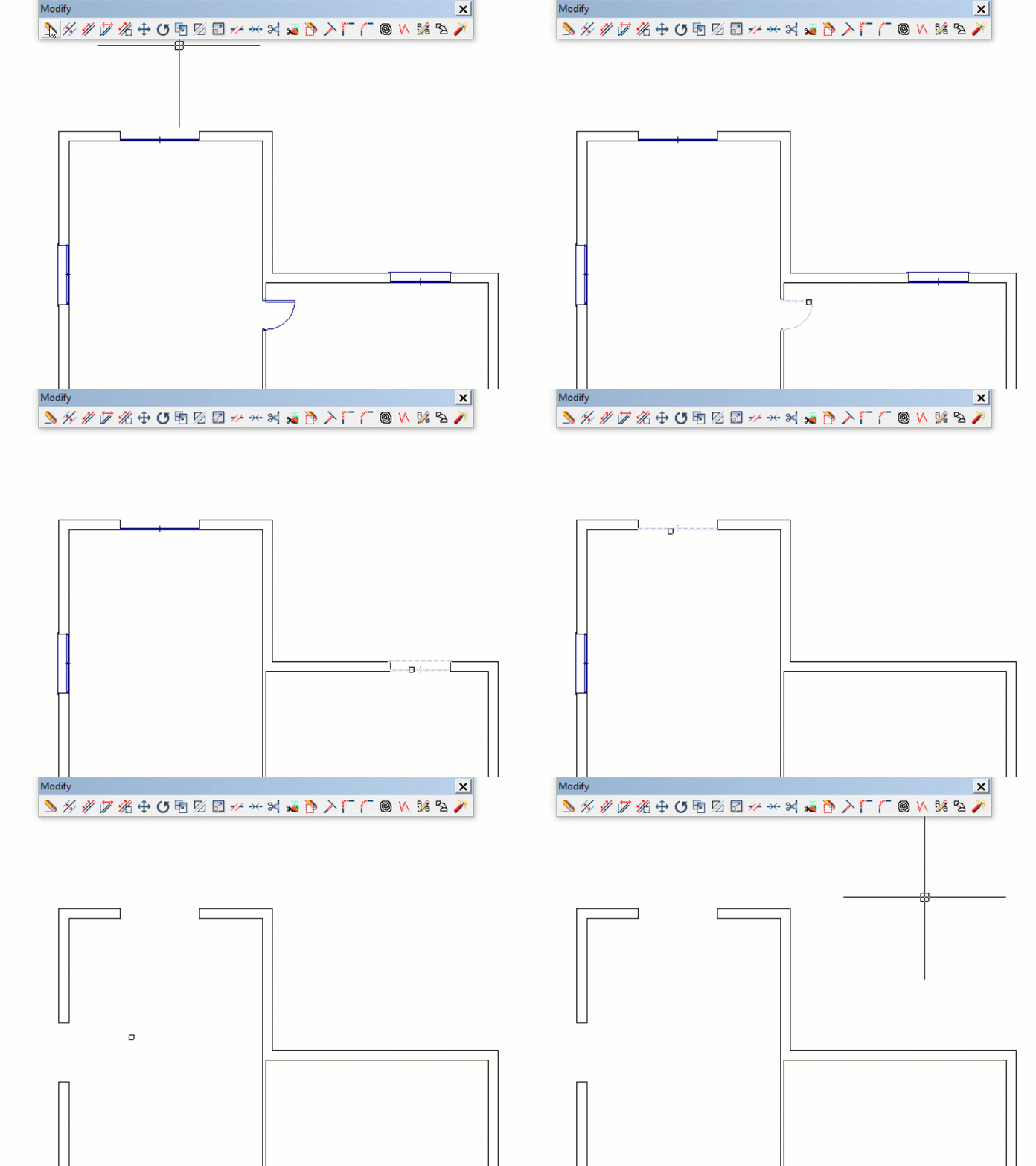
When deleting joinery items (doors, windows, wardrobe and user’s joinery), depending on the way of deleting, you will obtain different results:
• Delete items one by one, the function will rebuild the partition where the joinery item was located, unless the [ALT] key is pressed.
• Delete by selecting an area or more that one item at a time. All selected items will be deleted and none of them will be rebuilt.
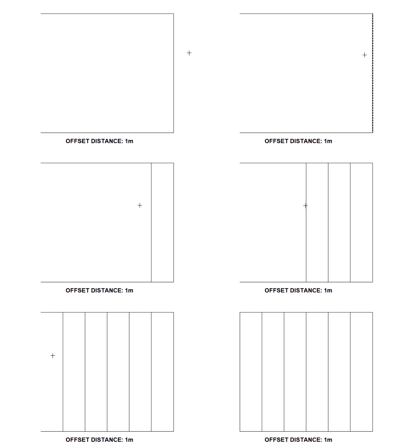
5.2.Offset
Commands: ‘PA’
This function allows you to draw a parallel line to a specific distance away from the following objects: [Line] · [Arc] · [Spline] · [Polyline]
 Enter the parallel distance or separation between the items in meters, and then press Enter.
 Next, select the item you want to offset (straight line, arc, spline or polyline).
 Then indicate the direction in which you want to offset. This way, you can consecutively draw parallel lines without exiting the function.
5.3.Lengthen - Shorten
Commands: ‘E1’
With this function, you can lengthen or shorten a simple straight line, an arc, a straight partition or a curved partition to the desired length.
To extend a wall or line, click near the endpoint. The cursor will be attached to the endpoint and an elastic line. By moving the cursor and clicking again, the whole entity will be lengthened or shortened up to the indicated position.
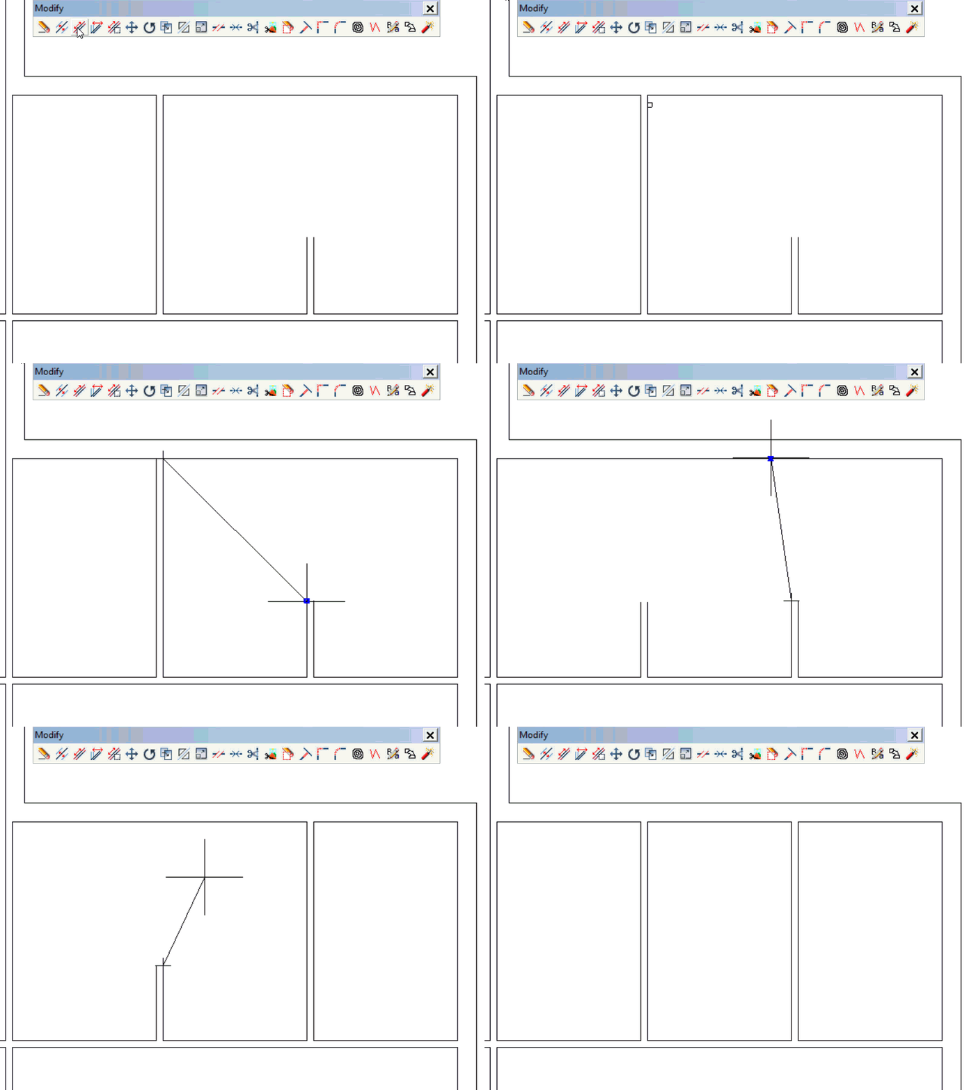
For walls, if you hold the Shift key and click on a side of the partition, only the selected line will be affected, while the other line remains the same without being lengthened or shortened.
If you want to undo the union of two walls (for example, the connection of a railing), first left click and then right click. The union closes automatically.
To make a join with another straight or curved partition, click on the outer straight lines if you want an “L” join.
If you want a “T” join, finish at the line closest to the wall that you are extending.
In the case of simple straight lines, the cursor will attach to the edge of the item, the elastic line appearing on it.
In lengthening or shortening curved walls, it is recommended not to indicate large arcs for lengthening, as you may get undesired results. It is better to choose shorter arcs to be lengthened and do the lengthening in two steps.
For two simple lines or arcs, there is another function [FILLET], which connects the two ends by extending the lines at the same time to their meeting point.
5.4.Turn and Pivot
5.5.Stretch area
Commands: ‘ES’
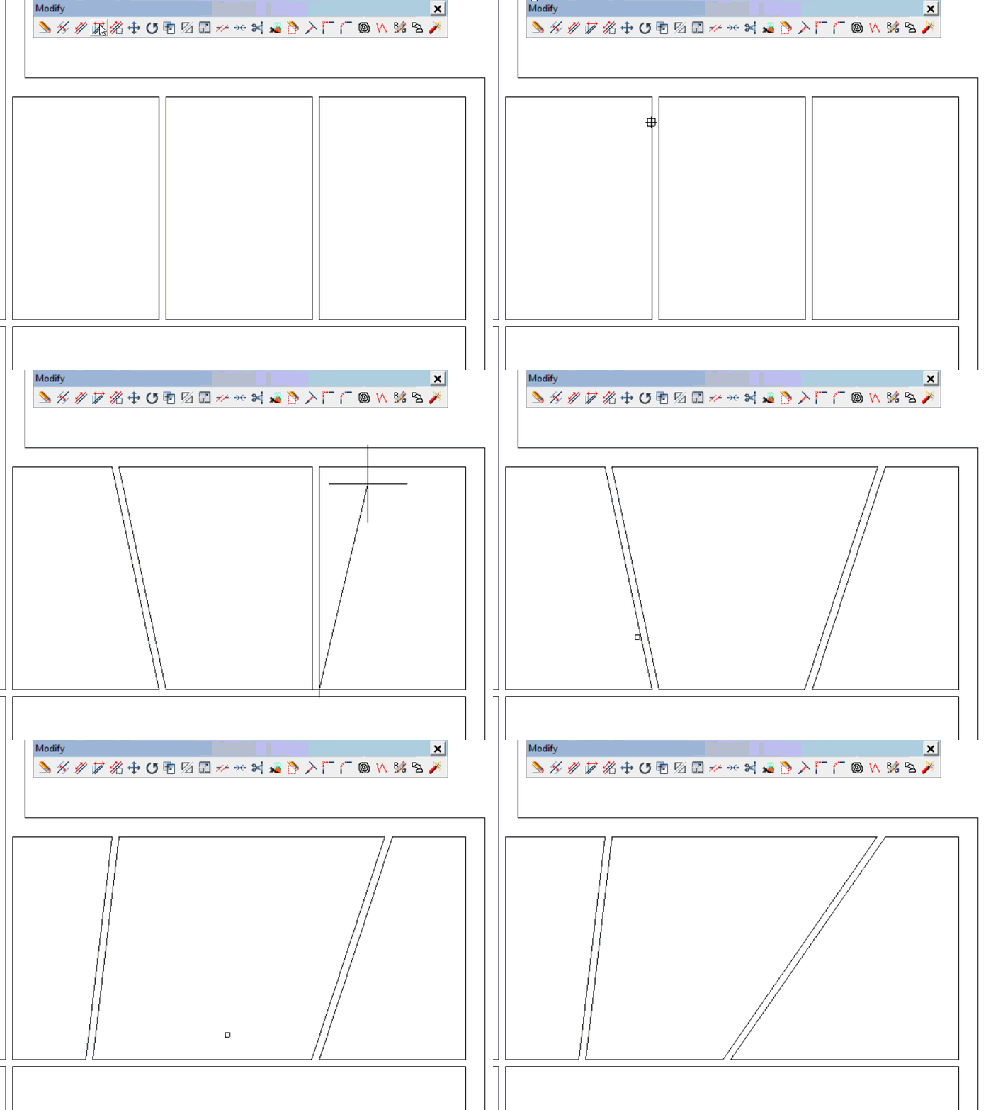
This function allows you to lengthen, shorten, stretch and move the geometry of a selected region.
 After the function is activated, select the area you want to stretch using the selection box.
 Then click for the initial point, move the mouse to stretch the geometry and click once again (or type a distance) to confirm the modification.
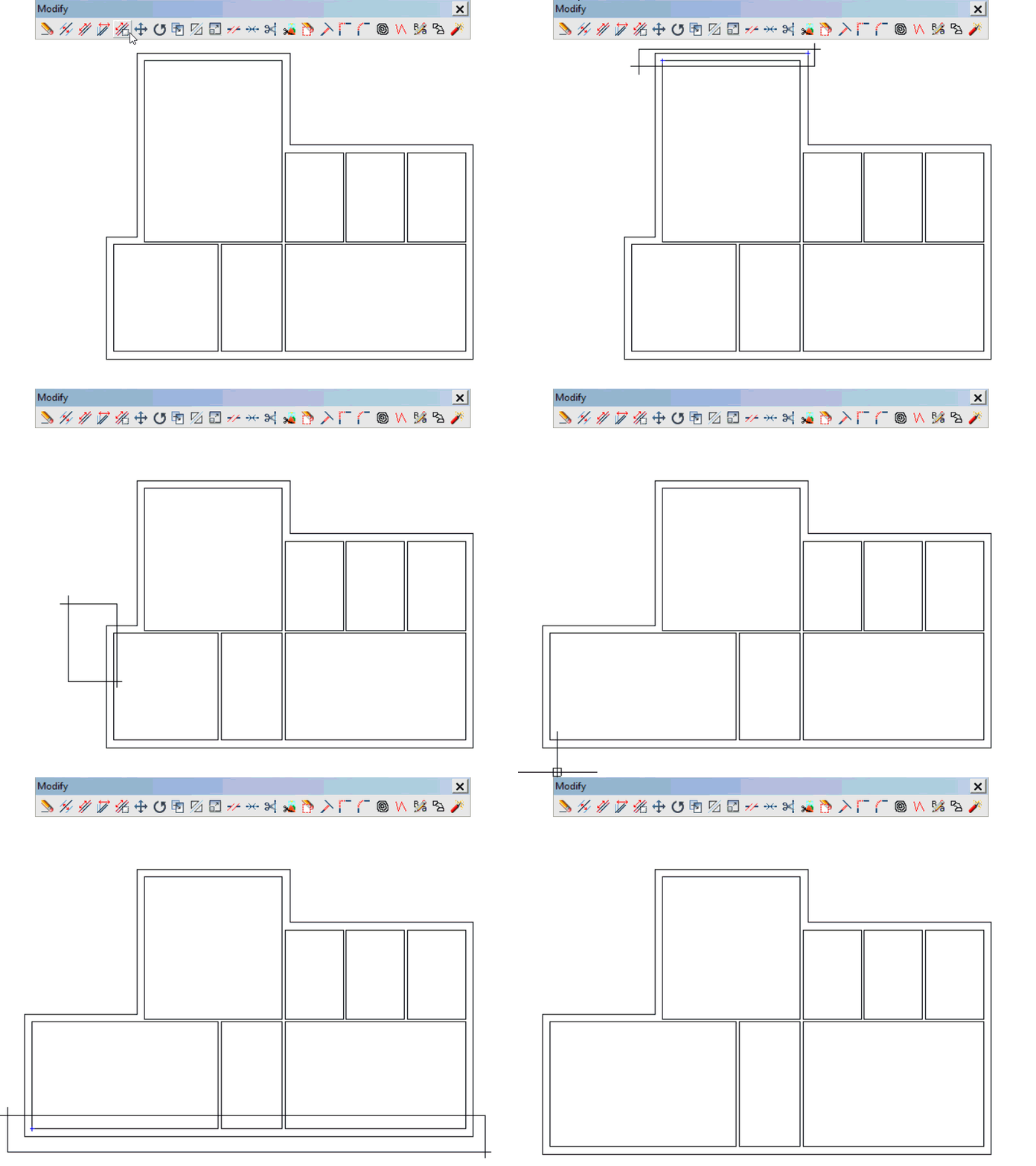
Moving the area
Moving the area can be done between any two points, or those pertaining to a straight line so that movement will be in the direction of this line.
If the orthogonality locking is enabled with H/V angle, this angle will represent the direction of the movement.
When creating a movement that affects certain size lines, they will be recalculated, with the new values of these lines appearing subsequently.
When moving walls, they should be free of joins with other partitions that you do not want to move. If not, you will get undesired results and will have to [Undo] the action.
5.6.Move
Command: ‘MOVE’, ‘M’
This function allows you to move objects in the drawing from an origin point to a final point.
The final point can be given with a distance entered with numerical keys (Enter).
 Once the function is selected, the first thing to do is to select everything you want to move by clicking on the items. Next, confirm the selection with a right click.
 Finally, click on the initial and final points. You can also click on the initial point, indicate a direction, and type the distance (Enter).
This function allows you to move objects in the drawing from an origin point to a final point.
The final point can be given with a distance entered with numerical keys (Enter).
Once the function is selected, the first thing to do is to select everything you want to move by clicking on the items. Next, confirm the selection with a right click.
Finally, click on the initial and final points. You can also click on the initial point, indicate a direction, and type the distance (Enter).
If orthogonality locking is enabled, the movement will be locked to this direction.
Copy while moving
You can make a copy of the selected objects using the move tool. To do this you need to hold the CTRL key while you indicate the initial point of the movement. After that click you can release the CTRL key and move the copy as usual.
Right after completing the first copy you can repeat this action to make multiple copies by typing asterisk + number (*n) and confirm with Enter or a right click, the first copy will be repeated n times with the same distance and in the same direction.
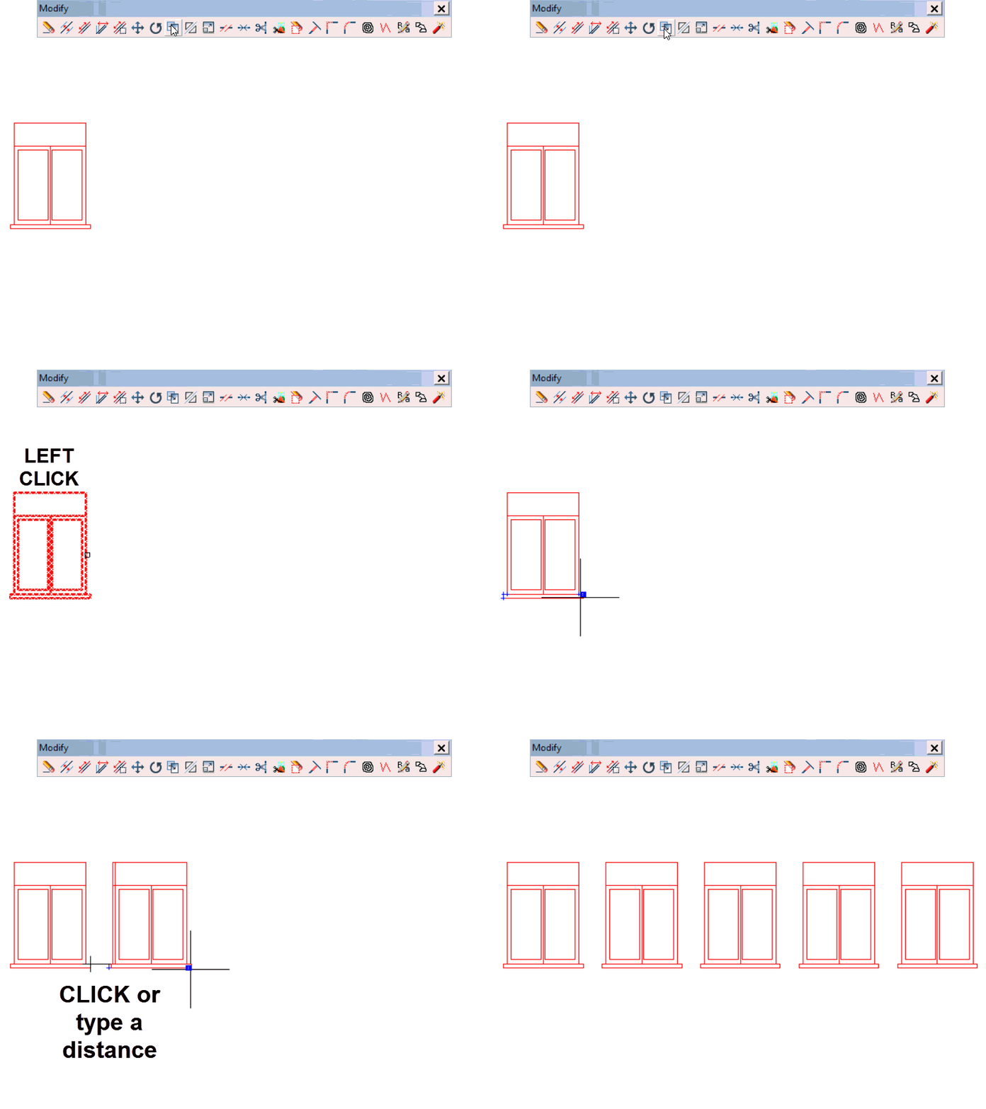 You can also divide two copies into equal parts. But this time, you use the original and the first copy. To do this, after making the first copy and, without exiting the function, enter division slash + number (/ n) and confirm with Enter or a right click.
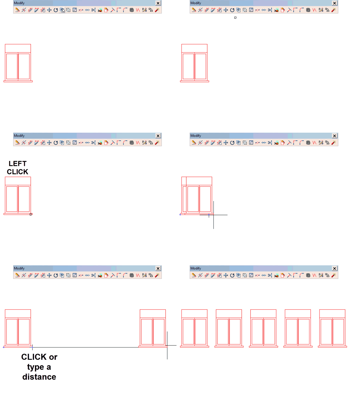 If you enter the wrong number of copies, just re-enter the correct number.
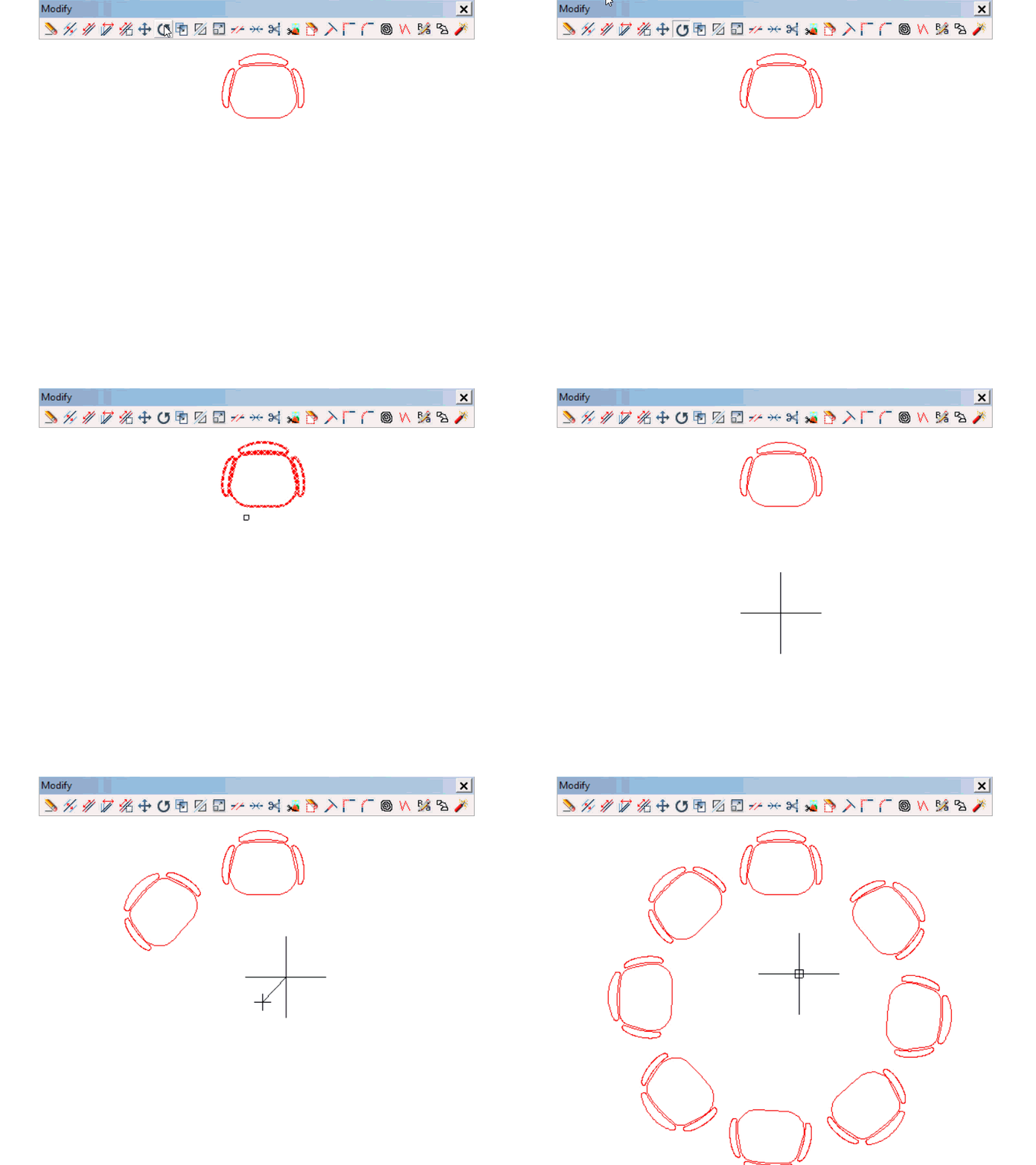
5.7.Rotate
Commands: ‘GIRA’ , ‘GI’
This function allows you to rotate selected items in the drawing at a certain angle.
 After activating the function, select anything to be moved by clicking.
 Confirm the selection with a right click.
 Finally, select the center of rotation, followed by the by the angle, directly using the cursor or by typing in the degrees (Enter).
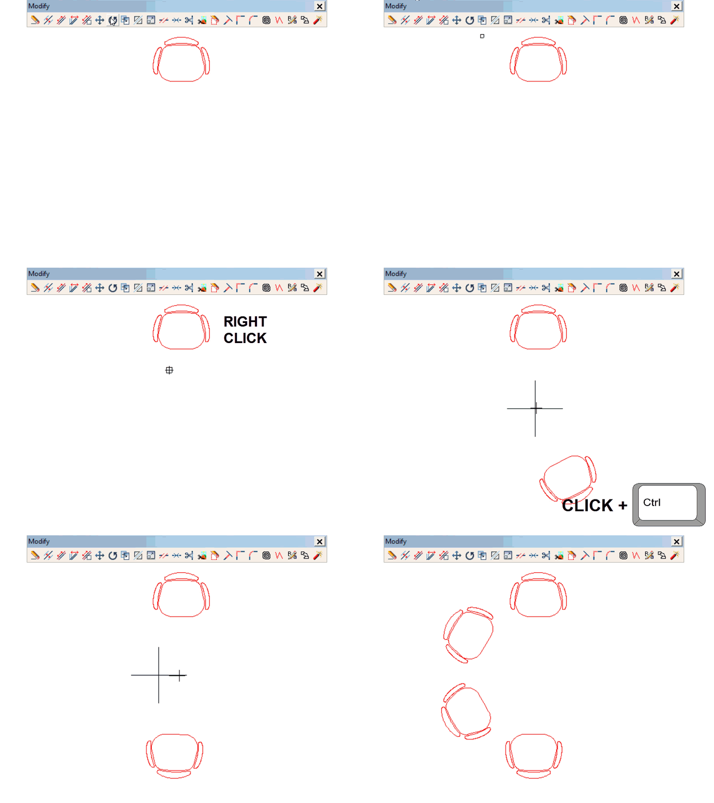
Copy rotating
To [COPY ROTATING], just press the Ctrl key upon marking the center of rotation.
If, after marking the first copy, you enter asterisk + number (*n) and confirm with Enter or a right click, the first copy will be repeated # times at the same distance and in the same direction.
For example, if you want to repeat it four times, make the first copy and type *4 immediately after the first copy is completed and confirm it by pressing Enter or right clicking.
You can also repeat copies by dividing the copies into equal parts. To do this, complete the first copy and, without exiting the function, enter the division slash + number (/ n) and confirm with Enter or a right click.
If you enter the wrong number of copies, just re-enter the correct number.
5.8.Copy
Command: ‘COPY’
This function allows you to copy any selected geometry right away from an origin point to a final point, as many times you want. It works the same as the copy function of the move tool but without the CTRL command.
 Once the function is activated, select everything you want to copy by clicking on it.
 Then confirm what you select with a right click.
 Finally, click on the initial and then on the final point, or you can also click on a start point, indicate a direction and type the distance (Enter).
As you move the cursor, you will see the drawing to be copied moving as well.
Multiple copy
If, after marking the first copy, you enter asterisk + number (*n) and confirm with Enter or a right click, the first copy will be repeated n times with the same distance and in the same direction.
For example, if you want to repeat the image four times, make the first copy and type *4 immediately after that, and then confirm by pressing Enter or right clicking.
You can also make copies by dividing the instances into equal parts. To do this, make the first copy and, without exiting the function, enter the division slash + number (/ n) and confirm with Enter or a right click.
If you enter the wrong number of copies, just re-enter * and the correct number.
CTRL + C (Copy in Windows)
Command: ‘COPIARPP’.
When a selection has been carried out beforehand, pressing CTRL + C (Copy in Windows) will move the selected items to the system memory. They can then be used with the CTRL + V (Paste in Windows) function, maintaining the items selected in their place and obtaining a copy of them.
5.9.Simmetry
Command: “Symetry”
This function allows you to obtain the symmetry of the selected items in the drawing in relation to a specific axis.
 Once the function is activated click to select the items (or make a selection box) and right click to confirm the selection.
 Once the selection is confirmed, click on an initial and final point of the axis. For example, vertical or horizontal. The distance between the selected geometry and the indicated axis will also apply to the symmetry.
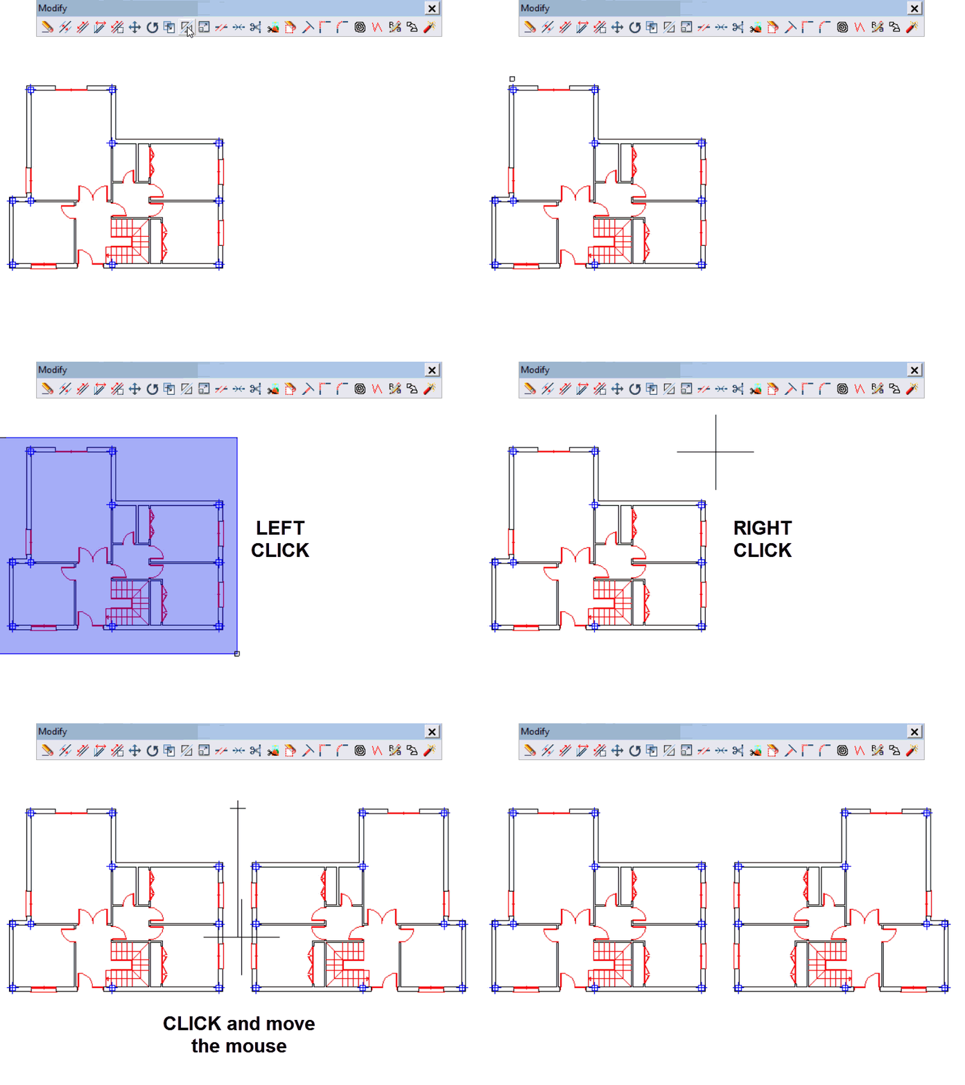
EXAMPLE OF SYMMETRY WITH A VERTICAL AXIS
We are going to make a symmetrical floorplan to the right of the existing one at 4 meters apart from the original. Check that ORTHOGONALITY H/V is activated (F8).
First, draw an offset line 2 meters away from the vertical east facade, which will serve as a guideline to mark your symmetry axis. Use the [Offset] function to do this ![]()
With the offset tool active, type 2 and press Enter. Click on the outer line of the east facade and then click to its right. A parallel line should appear 2 meters away. Right click or press ESC to exit the function
Now, activate the [SYMMETRY] function:
- Select the entire floorplan with a selection box and then confirm with a right click.
- Indicate the first point of the symmetry line.
- Next, indicate the second point (downwards).
The images then appear symmetrical in relation to the axis.
If you now want to repeat the horizontal symmetry of the two floorplans, it is necessary to select the recently created floorplans first because symmetry will only be made with what is previously selected.
5.10.Scale
Command: ‘ESCALA’
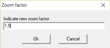
This function allows you to change the scale of specific items selected in the drawing indicating the scale center and a scale factor.
With the scale center as a fixed point, you can increase or decrease the scale of the items using the cursor or by typing the scale factor number that you want.
You can also scale a drawing or an image by giving an exact measurement between two points. If, upon giving the scale center, you hold the CTRL key down, the program will ask you to specify two points of the object and then the distance by which you want to separate these two points. Dibac will automatically calculate the scale factor needed so that it matches with the desired measurement.
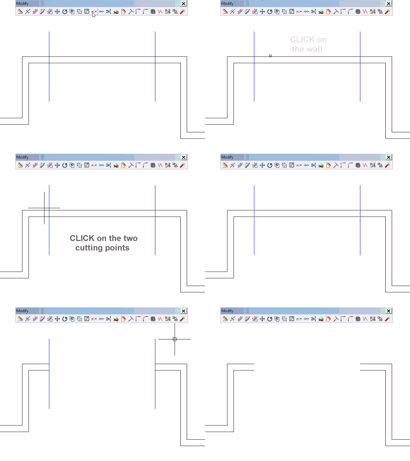
5.11.Split
Command: “SPLIT”
This function allows you to divide a straight or curved wall, a straight line or an arc.
Once the function is activated, click on the wall you want to separate. Then, using the mouse again, specify the two points that will divide the partition.
Note that it is not necessary for these points to be on the wall itself, as they can be supported by items outside of the wall.
In this last case, the partition will be divided exactly at the “intersection” points of these items.
Walls can also be split using the [Doors] function by selecting the [Doorway] option.
5.12.Join
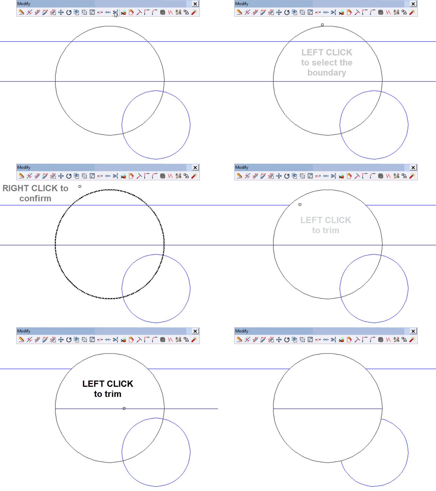
5.13.Trim
EXAMPLE
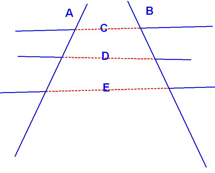
Let us look at an example of how this function works.
Start with the drawing that has 5 straight lines A, B, C, D and E. You want to crop lines C, D and E using the boundaries of lines A and B.
Enter the function.
- Click on line A and then line B. (These two lines will crop the rest [C, D and E]).
- Right click to confirm.
- Finally, click on lines C, D and E, which will be cropped between lines A and B.
Make sure to click on the section of the line that is going to be trimmed.
5.14.Crop image
Command: “Crop”
This is a different method to crop an image. This function is found in the [MODIFY] menu or toolbar. It allows you to crop an image using another entity (Rectangle, Circle, Ellipse, Polyline or Arc).
 First, draw the polygon that will crop the image.
 When you initiate the function, select the image to be cropped by clicking on one of its edges.
 Next, select the entity that will crop the image. Once this is indicated, zoom the camera and the image will be cropped
Unlike an untrimmed image that can only be selected by clicking on its perimeter, the cropped image will have its entire surface active, although for the approximations it will take the point of its perimeter closest to the cursor position.
To undo the cropping, use the same function. Any image you select to be cropped will again have its original dimensions. Do not forget to click on the center of the image rather than on its edge
5.15.Erase area
Command:
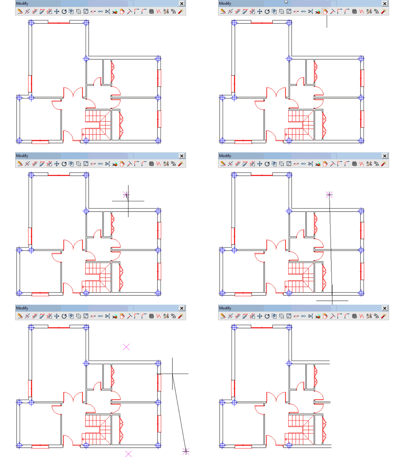
With this function you can define a “polygon” with three or four sides by indicating its vertices. This “polygon” will be the deletion area. All elements within this area will be cropped up to the polygon edges, except for joineries, pillars and blocks, which can only be deleted if they are completely within the area of the “polygon”.
With the function activated, the polygon deletion area is defined by clicking four times on the four vertices that you want. In the case of a triangular area, you will only have to click three times and confirm with a right click.
5.16.Extend
Command
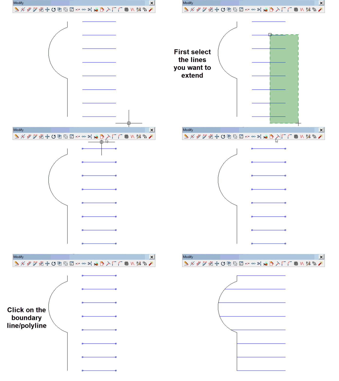
This function allows you to extend several lines in the drawing to one or more lines.
There are two possibilities:
1. Simultaneously extend several lines until they intersect with another one
 First, before selecting the function, select the lines you want to extend.
 Then select the function and click on the destination line.
2. Randomly extend several lines up to one or more destination lines.
 In this case, select the function first
 Then mark the destination lines by clicking on them and confirm your selection with a right click.
 Then click on the lines to be extended, which will extend one by one until they intersect with the first destination line they find.
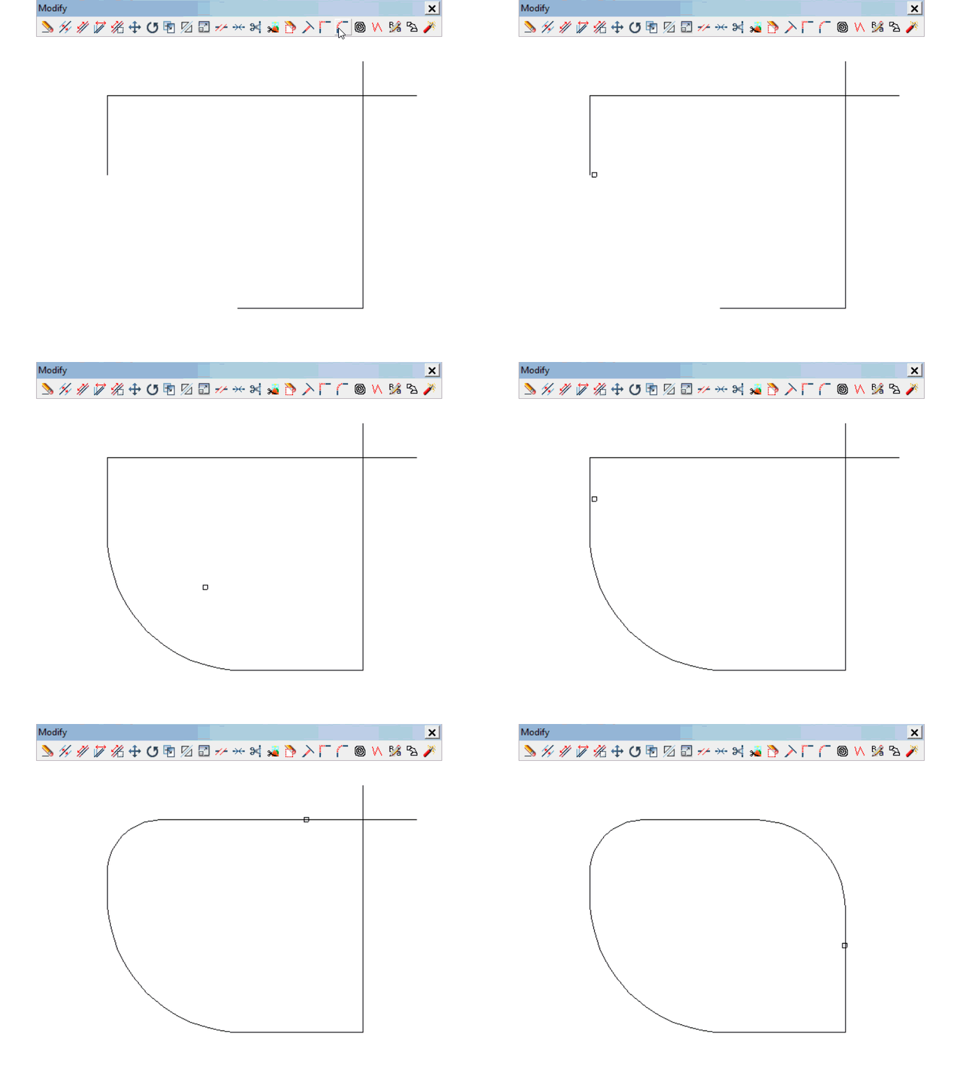
5.17.Fillet
Command
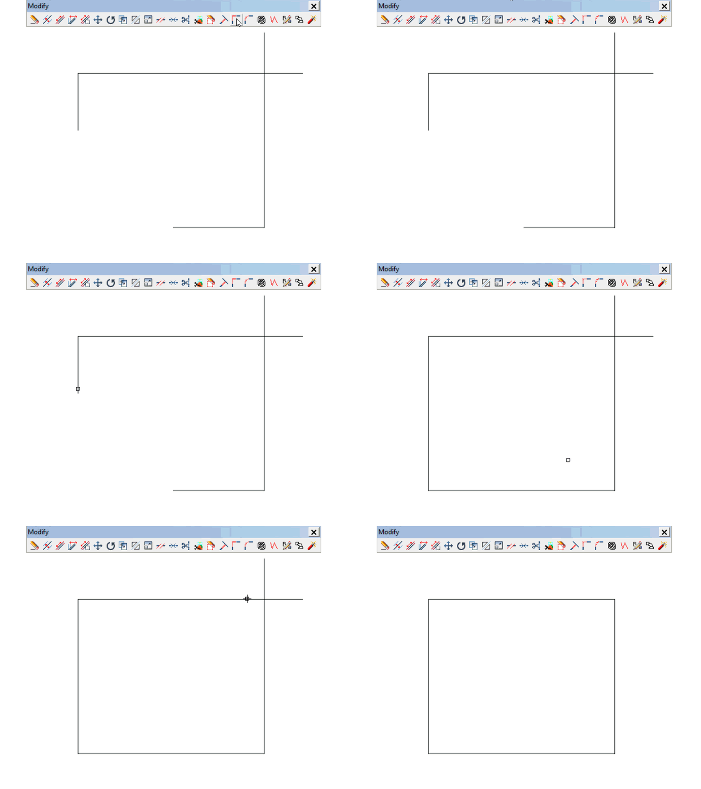
This function allows you to join two converging lines at their intersection point. Activate the function and click on the two lines to join them.
This function can also crop the parts of the lines that are already intersecting. For this, click on the sections of the lines that should remain visible after cropping.
5.18.Curved fillet
5.19.Curves to 3D
This function allows you to raise the plane of contour lines from 2D to 3D.
To do this:
 Click on the edit drop-down menu at the top and select the [CURVES to 3D] option.
 With the cursor in the shape of a small square, select all the curves that will be affected and right click to confirm
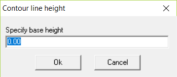
 A window should appear to specify the height of the base contour. Type in the value and click [Ok].
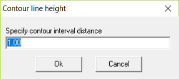
 The next window is to specify the contour interval distance between each contour line. Indicate the increment value and click [Ok]
 Click outside of the lowest curve. Move the cursor over all the curves in the direction of the highest one. Then click after passing the highest curve
5.20.Convert to polyline
5.21.Align
Command: “ALI”
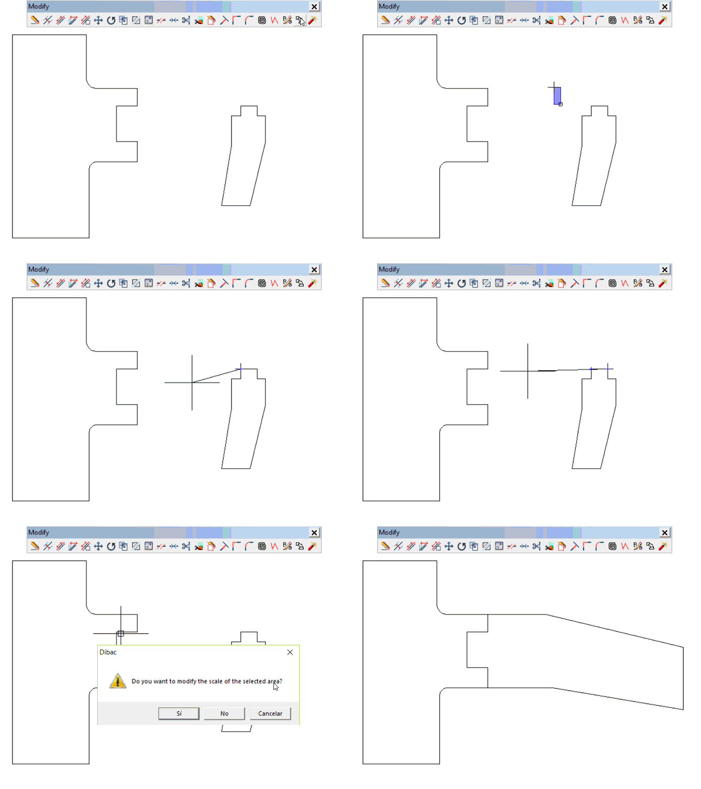
Use this function to move and rotate a selection of items to align it to another reference
To do this:
 Select the ALIGN function
 Select the item or group of items to move. Right click to confirm the selection
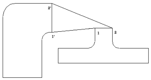
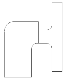
 Now, indicate a point (1) and its corresponding (1’) in its new position. Then, indicate the other point (2) and its new position (2’)
5.22.Explode
5.23.More Functions
The functions that you have seen are in the [Modify] menu, which appears in the top part of the screen.
Under this tab (Modify), there are three more functions: [Match properties], [Apply properties] and [Capture entity properties].
The three icons also drop down from the top horizontal bar in the [Standard] menu.
Match properties
Indicates the item whose properties you want and then all the items to which you want to apply these properties. To finish, right click.
Apply current properties
The current properties will be applied to whichever items you select. To finish, right click
Capture entity properties
When you select an item, all its properties (color, line type, size, etc.) will be stored to be applied to what is drawn later.
6.Consult Toolbar
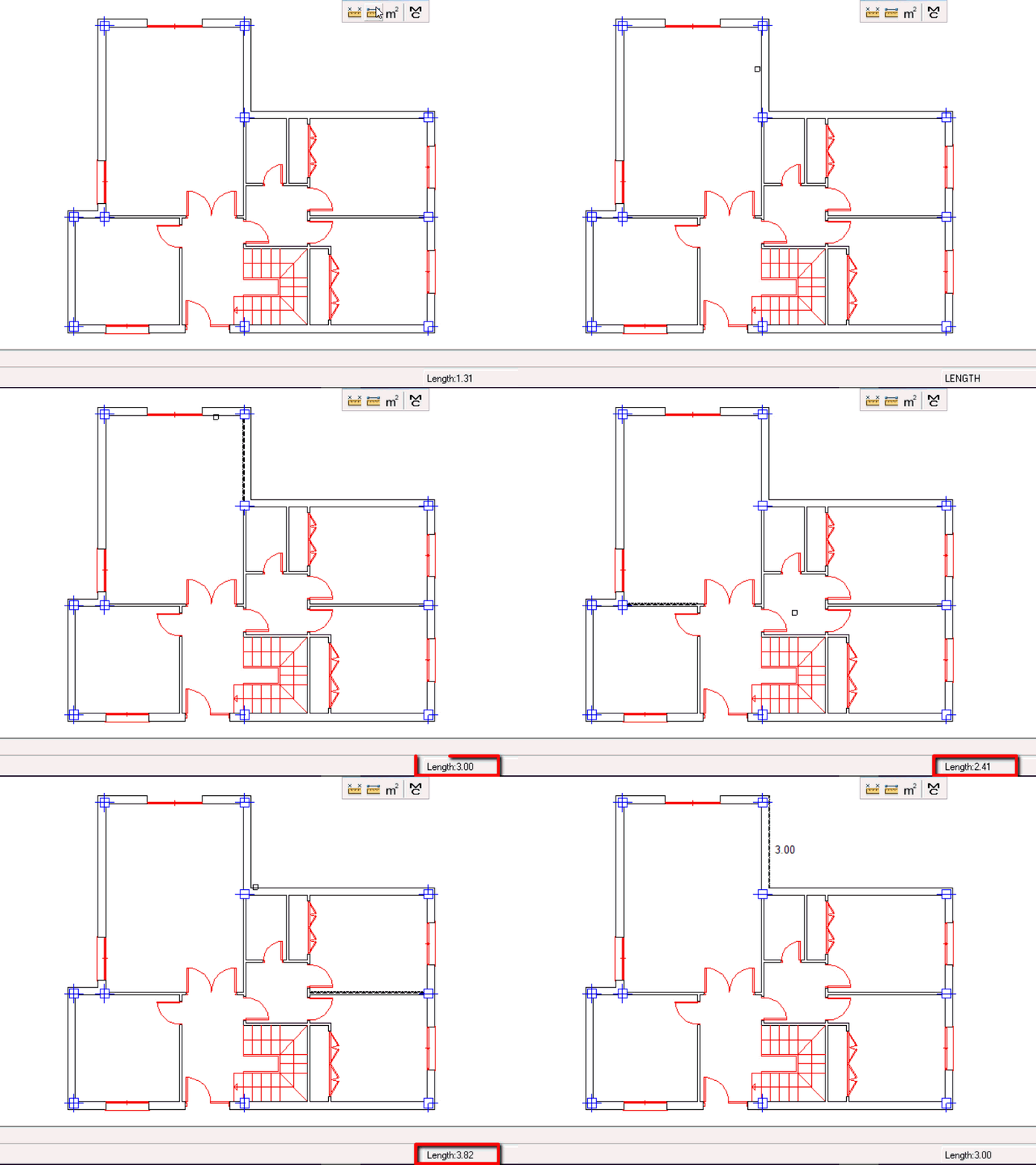
6.1.Distance
6.2.Length
6.3.Areas
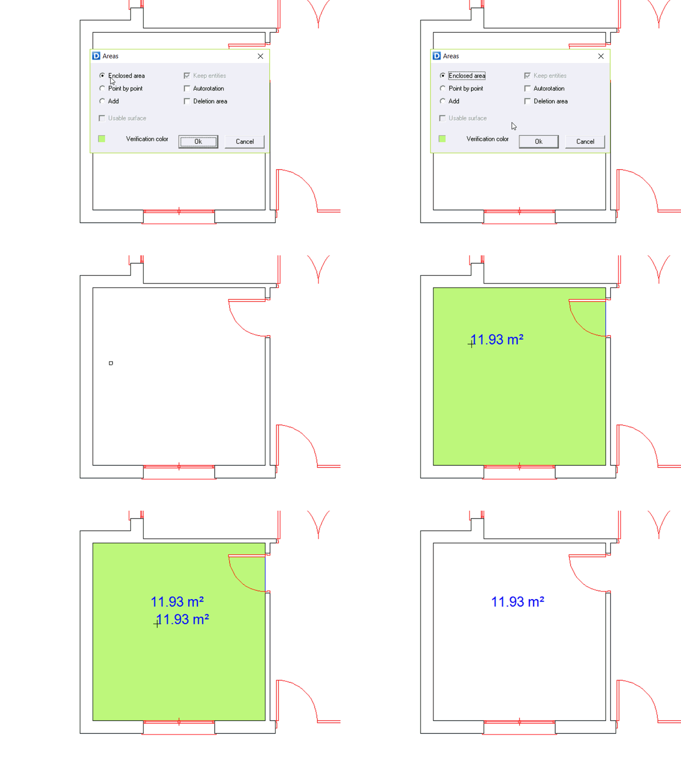
When you select this function, a dialogue box opens, in which you can indicate how you want to obtain the surface area:
Enclosed area
The surface area of an enclosed figure is obtained automatically just by clicking on one of its elements. You can also obtain the surface area of a hatch just by clicking on it. This figure can be an area, a polygon, a circle, an arc, etc.
First click on one of the lines of the enclosed area. You´ll see the highlighted area that shows the calculated surface. Place the area value with one click and then right click to finish the action.
Point by point
This is a manual method of obtaining the surface area. Just mark the perimeter, point by point, and then right click.
Add
Adds up all previously selected surface areas one by one, or with a selection window
Keep entities
This box refers to the previous [ADD] If this option is enabled, the surface areas that have been added up are conserved in addition to the text showing the total area value. If this is disabled, the surface areas added together disappear and only the result of the sum appears instead.
Autorotation
If this option is activated, the number obtained for the surface area is rotated to be parallel to the item on which you are placed.
Deletion area
When you place a surface area measurement with this option activated, it creates a masking area under the text so that it appears more sharply. For example, if the text is placed on a striped area, this box should be activated so that the text does not appear crossed by the stripes
Verification color
This allows you to change the checking color of the surface area you want to measure.
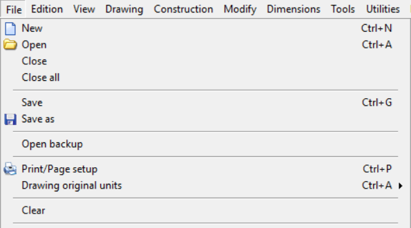
7.1.New
This function is used when you want to start a new drawing.
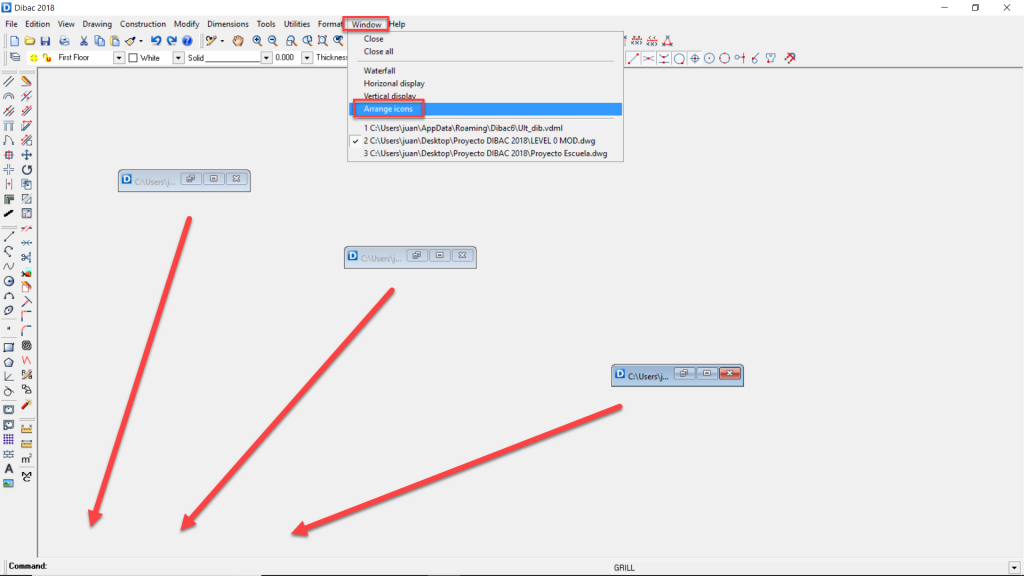
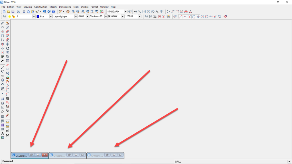
If you have a drawing open on the screen, it is minimized and the second new drawing is opened.
7.2.Open
This function allows you to bring to the screen a saved drawing in a storage unit.
You can also choose one of the last six drawings opened.
7.3.Close
With this you can close the current drawing.
7.4.Close all
This is used to close all open drawings.
7.5.Save
With this function, you save the current drawing in the same directory and the same file name. Be careful with this function, as you can accidentally save a modified drawing over another valid one.
7.6.Save as
This function is used to save the current drawing as a new file, after selecting a storage unit, directory and file name. By default, the drawing is saved in DWG format 2010 version.
However, drawings can also be saved using almost all existing formats.
7.7.Open a backup
Use this function to open any of the backup copies saved by the program as: CSD-02-04-2015 18-06-34, where “02-04-2015 18-06-34” corresponds to day, month, year and time of creation. In this example: April 2, 2015 at 18:06:34.
7.8.Insert file
This function is in the vertical menu. The icon and the process are the same for inserting blocks and files.
When you select this function, a window pops up, in which you can select a specific drawing from among the list of files of the preset library.
To do this:
 Click on: [File].
 Select the file you want to insert.
 Click [Open]. A preview of the file should appear in the window.
 After clicking [Ok], the file can be inserted into the drawing.
This file is inserted as if it were a block, therefore you can explode it later.
7.9.Insert external reference
This function is located in the vertical menu. The icon and process are the same as the one used to insert blocks and files.
An external reference is a file that does not belong to the drawing that, nonetheless, is displayed within the drawing.
Although an external file cannot be modified within the drawing, its great advantage is that once it is modified outside of the drawing, it is changed in all the drawings in which it appears using the Regenerate function (Ctrl+S)
When you select this function, a screen opens from which you can select a specific drawing from among the list of files belonging to a directory, to insert it as an External reference.
To do this:
 Press Ref. Ext. [External Reference]
 Select the file you want to insert as an external reference.
 Click [OPEN]. A preview of the file should appear in the window.
 After clicking [Ok], you can insert the file into the drawing as an external reference.
This file is placed as if it were a block. Once it is inserted, it cannot be modified or exploded from within the drawing.
If you want to modify an external reference, open it separately. The changes you make in that file will be reflected immediately in the drawings in which the external reference appears.
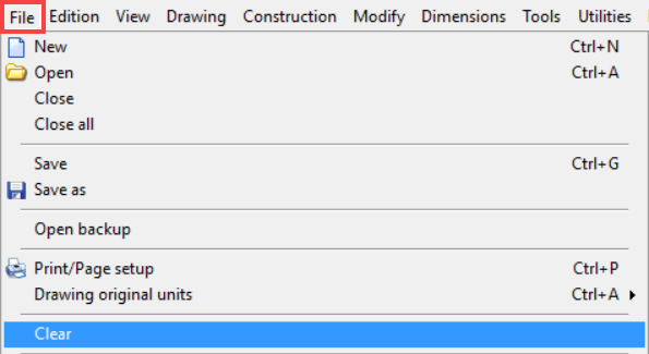
7.10.Purge
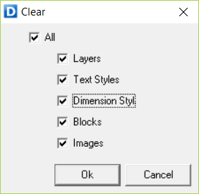
When you enter this function, a window appears in which you can select the objects of the drawing you want to delete.
This function implements a series of internal instructions to purge unusable items in the drawing, as well as deleting empty spaces. It gives you the chance to delete empty layers, thus reducing the size of the debugged drawing.
This function will purge the blocks (objects) from the drawing that do not appear on the screen due to having been erased from it at some point, but only when their layers are active. If there is a locked or frozen layer, their blocks will not be deleted.
It is recommended to purge the drawing before saving it to disc.
7.11.Exit
This option returns to the operating system without asking if you want to save the drawing on the screen.
This drawing will remain on the screen when you enter the program again.
Any electricity outage will not affect the drawing, as it is permanently stored on the hard drive, unless the outage causes this hard drive to crash.
7.12.Backup copy
Dibac automatically makes backup copies every 15 minutes, saving them to a directory called SEGFILES, located in the main program directory, which makes it very difficult to lose files.
The saving interval can be modified in the menu: [Tools} – [Preferences] – [General] – [Backup Copy Interval].
7.13.Print/Page setup
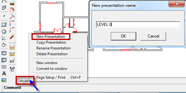
To print a drawing at a certain scale, it is convenient to see it on screen beforehand as it is in the paper format that we are going to use in the plotter or the printer.
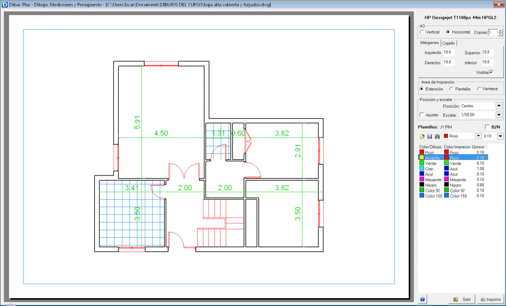
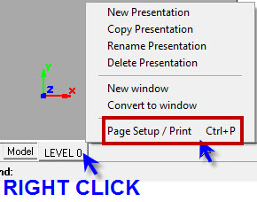
Click on the [Print/Page Setup] option in the [File] menu.
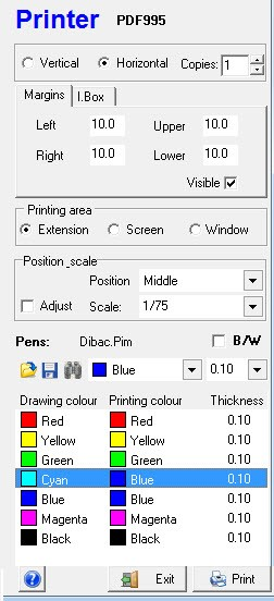
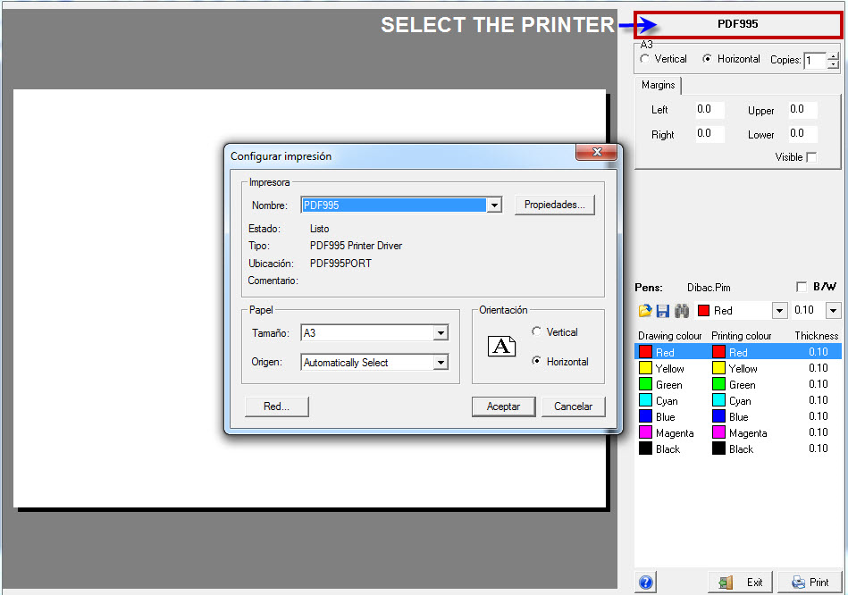
A screen opens in the paper format, where you can see how the drawing looks and how it will print. This screen has a dialogue and configuration menu on the right-hand side.
Let’s see the different options on this menu:
Printer
First, you can check the name of the current printer. To change the printer, just click on its name and the Windows printer setup menu appears. On this menu, you can change the printer and adjust its parameters by clicking on the [Properties] button.
Paper position
Vertical or Horizontal. Checking one of these options will change the position of the paper onscreen.
Number of copies
This allows you to print many copies of the same drawing at one time.
Margins
By changing the margins, the position of the drawing on the paper is modified. These margins are defined in millimeters. The margins will be visible on the screen by activating the corresponding box
Printing area
[Extension]. With this option enabled, the entire drawing is displayed, but with a certain scale and position
[Screen]. This is similar to the previous option, but it will keep the scale and position established in the drawing.
[Window]. This option allows us to view and print just one area of the drawing. To define this area, click on the word [Window]. To activate the option, just click on the circle next to the word [Window].
Position and scale
[Position]. This allows different automatic positions on the paper. Just click on the arrow and select the one that you want.
[Adjust]. This checkbox adjusts the drawing to occupy the entire sheet (respecting the margins), giving us an approximate scale. Equivalent to Extension Zoom.
[Scale]. To enter a specific scale, the [Adjust] option must be deactivated. To select a scale, just enter its number. Keep in mind that the scale can be written in the format n /.
For example, you could type 1 / 1000, and also 2 / 1000, 3 / 1000, … n / 1000.
By pressing on the arrow, you have the most commonly used scales to choose from.
Pens
This part of the printer menu allows us to define the print colors as well as line thickness in the printer (pen number).
The word pen refers to the old pen plotters, which had thicknesses of 01, 02, 03, etc. defined by tenths of a millimeter.
In modern printers, these thicknesses can be defined by hundredths of a millimeter, so a thickness of 01 would presently be 0.10 mm. (10 hundredths of a meter).
On the first line of this part of the menu, to the right of the word “Pens”, you can see 1.PIM. This means the set-up file that you are using at this moment is 1.PIM. The PIM extension means [Printing Screen].
On the next line, there are three icons plus the [Color] and [Thickness] boxes.
Icons
 [Open] the print setup file.
 [Save] the print setup file.
 [Print Preview] only selected colors. Select the colors you want and then click on the icon.
Color box
The color box allows you to choose a color from the column of printing colors to be applied later.
Thickness box
The thickness box allows you to select a thickness from the column to be applied later.
Drawing color · Printing color · Thickness
At the bottom of the printing menu, there are three columns:
[Drawing Color] column. Shows all the colors used in the drawing.
[Printing Color] column. Shows all the colors as they are going to be printed.
[Thickness] column. The thickness of the lines of each color when printed.
Each drawing color corresponds to the printing color and the thickness given in its row.
The drawing color is fixed. To change the printing color, just select a color from the color box and double click on the printing color you want to change. You can also select a color by double clicking on any drawing color and then double clicking on the printing color you want to change.
To change the thickness, just select a thickness from the thickness box and double click on the one to be changed.
You can also select several rows at the same time and assign the same color or same thickness.
8.Layouts
This function allows you to display one or more views of the drawing (Model) at different scales and with different layers’ visibility.
This enables you to design the paper space and the content that will be displayed in each layout.
8.1.Create a Layout
To create a new layout:
 Right click on the [Model] tab located in the lower left-hand side of the screen. Select [New Layout].
 A window should open where you can enter the name of the layout. Enter a name, for example: LEVEL 0.
 A blank sheet of paper will appear on the screen with a default paper size. This is called the paper space.
You can Press F3 anytime to center the paper space on the screen.
8.2.Change page setup
 In the following window you can select the printer, the paper size and orientation of the paper space.
In this example, the paper size is A3 HORIZONTAL
 Click [Exit] to return to the “LEVEL 0” layout
Press F3 (Extended zoom) to see the layout page centered 
8.3.Create a viewport in the layout
The viewport is the window that will display the drawing of our project (model) in the paper space.
By default, a new layout doesn’t have any viewports when they are created.
Create a new viewport
To create a new viewport:
 Right click on the tab and select [New viewport].
 Draw the viewport on the paper space by clicking once for the first vertex and once again for the opposite vertex.
Moving, rotating and changing the width and height
Once the viewport is created you can move it and rotate it using the respective tools in the Modify toolbar.
If you left-click once on the viewport, you will be able to move the corners of window by clicking once on one of the corner grips and clicking once again to confirm the new position of the corner.
You can change the width and height of the viewport using the [Stretch Area] function. Select the side you want to extend/shorten and move it with the orthomode on.
8.4.Enter the viewport
8.5.Exit the viewport
To exit the viewport, you have to double-left click outside the viewport.
8.6.Set layers in the viewport
Every time you create a new layout, you´ll get a layer group in the Layer manager window. This Layer group includes all the layers of the drawing and indicates their status in that particular layout.
You can access the [Layer Manager] in the Layer toolbar.
A window opens where you have the name of the layout in the left column and the status of the layers in the right column. Here you can freeze and unfreeze the layers that you need. Make sure to press “Apply” to keep the changes.
This will set the visibility of all the viewports in the same layout.
After doing this, if you want to set the turn on or off the layers of a specific viewport of the layout you can double click on the viewport and set its visibility through the layer’s dropdown menu.
8.7.Create a second layout
8.8.Design viewport in the second layout
 First, set the layer’s visibility in the Layer manager window
– Select the [Layer Manager] option
– A window appears in which you can deactivate or activate the layers you need. Select the LEVEL 1 group. In this case, activate the layers [1 FORMAT] and [LEVEL 1] and deactivate all the rest. [Apply] and [OK].
 Double click in the viewport to enter the model
 Center the ground floor in the viewport and set the scale in the corresponding box.
In this example, 1/50.
 Finally, double-click outside the viewport to exit the edition
8.9.Create a third layout with drawings at different scales
 Duplicate the previous Layout. To create the third layout, you can use the previous one as a reference:
-
Right click on the tab of the previous presentation: [LEVEL 1].
-
Select the option: [Copy Layout].
-
Type a new layout name, for example: LEVEL 1 LEVEL 0 AND SITUATION.
You´ll get a duplicate of the previous layout.
 Set the Layers visibility.
-
Select the [Layer Manager] option

-
A window appears in which you can enable or disable the layers as needed for the layout. In this case, activate the layers [1 FORMAT], [LEVEL 0], [LEVEL 1] and [SITUATION] and deactivate the rest.
-
[Apply] and [Ok]
 Edit the viewport.
-
Double click inside the viewport to edit it.
-
Centre the ground and first floors by panning or pressing F3.
-
Type the scale in its box. In this example, 1/100.
-
Finally, double click outside the viewport to exit the edition.
 Leave space for a new viewport.
-
Select the viewport and raise the lower edge. This way you leave space to create another viewport, where you can insert the location site with a scale of 1/200
 Create a new viewport.
-
Right click on the tab of the presentation/plane [GROUND FIRST] and [LOCATION].
-
Click on [NEW VIEWPORT].
-
Draw a viewport on the bottom-left hand of the paper space.
-
Center the situation plan. Type the scale in its box. For example, 1/200.
Now you have a third layout created and ready to be printed, with the viewports at different scales.
8.10.Line styles in the layout viewports
When a layout viewport is created, it is drawn within the CURRENT LAYER and with the color and line type attributes that are active at the moment.
Change the color/line type attributes
-
If you want to change the color of the viewport, select it and click on another color.
-
If you want to change the line type of the viewport, select it and choose another line type.
Make the lines invisible
To make the viewport lines invisible, select the viewport, open the line type menu and select: “[OTHER] > [INVISIBLE]”.
8.11.Layout frame: margins
With Dibac, you can easily define an exact print frame FOR EACH LAYOUT, even if you change the printer from one layout to another.
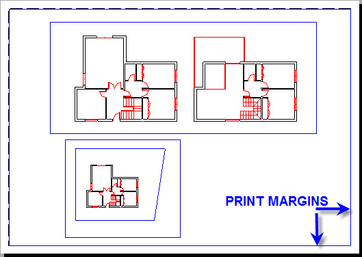
To do this, proceed as follows:
 Select a layout by clicking on its respective tab. For example, [LEVEL 0]. In this example, two lines appear around the drawing:
-
The first one in red is the drawing viewport defined in the layout. It is set as visible lines. (Remember that you can hide it by just clicking on it and selecting [Line type] [Invisible].)
-
The dashed line is the planned printing area depending on the selected printer.
 Right click on the tab of the layout [LAYOUT LEVEL 0]. Next, click on the option: [Page setup/Print]
 On the [Margins] tab, activate the [Visible] checkbox. The Printing frame will be visible.
 Then enter the margin values that you want.
-
Note that these values are in millimeters.
-
In our example, we entered 10 mm.
The printing margins are fixed automatically and become 10 mm smaller on each side.
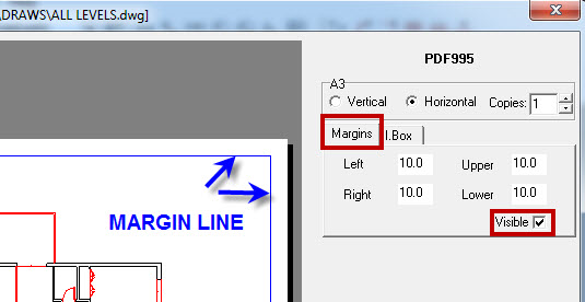
8.12.Layout title block
First, you must create a title box as a block. We suggest you create the box that you normally use in your planes as an object and save it.
In our case we have drawn, in real size, a simple title block without considering the printing scale, since it is not necessary on this occasion. We have given it the name of “TITLE BLOCK EXAMPLE”.
To insert the title block in the layout:
 Activate the first layout by clicking on the tab: [LEVEL 0].
 Then right click on the tab and select [Page setup/Print].
-
Activate the [INFORMATION BOX]
-
Click on the icon
-
Click on [File] to search for the title box block.
-
Check the VISIBLE checkbox. The box will appear, but it might be out of range.
-
Enter the box measurements in millimeters. [Exit].
When you click exit, you will return to the layout.
 Now you can introduce the texts of the title block, making sure to check the box “Title block” before placing the texts.
This will make it so that if the position of the title block changes, the added texts will be attached to it.
8.13.Convert to viewport
You can transform any polygon into a viewport as long as its lines are polylines.
For example, to convert a circle in the layout into a viewport:
 Go to the layout tab and click on “Convert to viewport”.
 Now select the polygon and it will automatically start to display the content of the drawing.
 Press F3 to center the drawing and change the scale and layers as shown before.
9.1.Undo (Ctrl + Z)
This function returns the drawing to the previous state, being able to go backwards as many times as we want, until the beginning of the drawing, as long as we have not activated the “Clean” function in the “File” menu, or do not open another different drawing.
The same effect can be obtained by pressing the Ctrl + Z keys at the same time, or clicking on the icon on the menu at the top of the screen.
9.2.Redo (Ctrl + Y)
This function recovers only one step, the last one from the situation that was reversed with the Undo function.
9.3.Cut (Ctrl + X)
Commands: “CORTARPP”, “CPP”
When you activate this function, the selected items will be passed to the system memory to be used with the [Paste] function, disappearing from their initial location.

 This function can also be activated with CTRL + X.
9.4.Copy (Ctrl + C)
Command: ‘COPIA’
This function allows you to copy items selected in the drawing as many times as you want, selecting origin and destination points.
These items may be placed at a distance entered with the numerical keys + Enter, in the direction of the cursor.
 Click to select items
 Right click to stop selecting.
9.5.Paste (Ctrl + V)
Command: ‘PEGARPP’
When you activate this function, the items selected with the [Cut] or [Copy] functions (which have been previously stored in the system memory), will be placed in the same or a new file. If the copied items are compatible with other software, they will be also pasted.

 This function can also be activated with CTRL + V.
9.6.Paste in place
Similar to the “Paste” function but with the difference that those items “copied” or “cut” are placed automatically in the same coordinates of the original.
9.7.Erase
Commands: “BORRA”, “B”
This function will erase any item located under the cursor. To use it, left click on the item and confirm with a right click.
-
If you click once, move the cursor from left to right, and click again in the opposite vertex, you will create a blue window. This way you will delete all the items that are completely inside the erase window.
-
However, if you move the cursor from right to left, all items with an endpoint in the erase rectangle will be deleted. If an element has its origin in the erase rectangle (for text, objects or polygons), the item will be deleted.
Delete key
When not using the Erase function, you can enter it by pressing the Delete key. With this function, you can erase any item in the drawing.
 First, select the items to be deleted, individually or by selecting an area with the cursor.
 Then press the [DEL] key.
How to delete joinery items
When deleting joinery items (doors, windows, wardrobes and user’s joinery), depending on how you delete them, you will obtain different results:
-
Deleting items individually, the function will rebuild the partition where the joinery was located, unless the key [Alt] is pressed.
-
Deleting by selecting an area: all items selected will be deleted and any of them can be rebuilt.
-
If selecting more than one item individually, joineries will be deleted leaving notches unless they have also been selected.
9.8.Search text
-
 If you press “S”, Dibac will search the following text with the same letters.
  Pressing “N” exits the function.
-
By default, the search option does not distinguish between caps, vowels containing accents or not.
-
If you introduce several words, it will search texts containing those words without considering their order
-
To search a specific text, insert words in quotes. By doing this, it will only search those texts containing all words introduced in the same order.
10.View Toolbar
10.1.Redraw
This function cleans the screen and updates certain changes that are not visible at first glance.
It is used to see the screen clean of undesired visual effects.
10.2.Regenerate (Ctrl + S)
10.7.All
10.8.Extension (F3) · Complete drawing
10.10.Selection Zoom
10.11.Viewpoint · Rotating X,Y axis
This controls the rotation of the coordinate axes that appear in the lower left-hand side of the screen.
This function allows you to rotate the workspace to see it from any point of view, without actually moving the drawing from its place. This function actually rotates the background with its coordinate axes, and not the drawing (which stays the same with respect to the coordinate axes).
It is very useful for irregular drawings and in drawing all elevations and sections on a floor.
To change the point of view, change the angle value in the Orto [Orthogonality] H/V box and press the icon.
You can also do it by entering the angle and typing PV, then by pressing the Enter key.
Note that the angle of any straight line or wall can be “captured” with the selection function. To do this, place the cursor on top of the line or wall and press F8. You will see that the cursor changes its orientation and the H/V angle is updated.
11.Dimensions Toolbar
11.1.Current dimension style
11.2.Define dimension style
When you enter this function, a window opens in which you can change the current dimension style, or create a new one.
The options are:
-
Style name. The default style is STANDARD
-
Create a new style. If you select this option, a window appears where in which you can enter the desired name for of the new style. [Ok].
You can define the following parameters for both the new style and the current one:
11.2.1.Base line
ACTIVATE – DEACTIVATE. It refers to the dimension line
11.2.2.Ordinate dimension (Continuous Dimension)
Activate – Deactivate. This allows you to mark the origin (straight-line measurement) using the [Continuous dimension] form.
11.2.3.Extension lines
These segments join the ends of the dimension lines with the indicated points of the drawing. With the extension option you can indicate a specific dimension for these segments.
-
Line color. When you click on the color box, a color table appears in which you can select the line color for the dimension lines.
-
Extension. This refers to the length of the extension lines when they are activated.
-
Origin distance. This This is the distance from the point marked to where the extension line begins. You can define this distance and the visibility [Activated – Deactivated].
11.2.4.Arrows
-
Arrow types. Form of notation on the ends of the dimension lines. When you click it, a drop-down menu with different types of arrows and segments opens.
-
Arrow sizes. You can specify the size of the different arrow symbols.
-
Scale factor. The scale factor should be one by default.
-
Changing this factor allows you to set the dimensions of the drawing in cm, mm, etc. For example, dimensioning in centimeters has a scale factor of 10. Dimensioning in millimeters has a scale factor of 100.
-
This is also useful when using the dimensions in drawings at a distorted scale or out of scale. For example, if the scale factor is 2, something measuring 4 meters is displayed as measuring 8.
-
11.2.5.Text
-
Dimension text color. By clicking on the color box, a color table appears from which you can select the text color.
-
Dimension text size. This allows you to define the ordinate dimension size.
-
Dimension text font. Here you can select a text type previously defined in the general text menu [Format] – [Text style].
-
Dimension text orientation. In this option, a drop-down window lets you choose between:
-
Aligned to the dimension line. This writes the text in the same direction as the dimension line
-
Horizontal. This always writes horizontal text.
-
-
Position of the dimension text. Two options: Within the line or Above the line.
-
Separation of dimension text. This acts only when the text is within the dimension line. It refers to the space that opens to accommodate the text in the dimension line.
11.2.6.Minimum thickness
This function allows you to define a minimum thickness to be displayed in the dimensions. Any value below the defined measurement will not be displayed.

For example, this function is very useful when you want to ignore the walls and partition thicknesses in the dimensions. Just type 0.26 m. so that the house is dimensioned from side to side (automatic Dimension), except for 25-cm walls, 10-cm partitions, 7-cm partitions, etc.
11.2.7.Dimensions linear units
See: Tools / Preferences / Drawing Units
The Drawing Units are those that define the real size of the geometries.
The Dimensioning units only show a measurement sign and, to consider them correct, they must be in agreement with the Drawing units.
Type of dimensioning linear units. You can choose from 3 options:
- DECIMAL METRIC SYSTEM
- FEET – INCHES ENGINEERING
- FEET – INCHES ARCHITECTURE
Precision of units. (No. of decimal points / Fractions)
11.2.8.Angular units
-
Type of angular units. You can choose from among several types of angular measurement that appear in the drop-down menu: [Angle decimals] – [Degrees, minutes and seconds] – [Grads] – [Radians]
-
Precision of degrees (tenths of degrees). You can define the precision for all types of angular units.
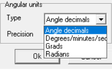
11.3.Linear dimension
Commands: “ACOLINEAL”, “ACOLI”
This will dimension between two points, in the direction indicated in the rotation window of the H/V cursor.
These two points do not have to be aligned, although the dimension will be aligned with the H/V angle (ORTHO).
In the adjoining image, you see that although the points with the dimension are not aligned, the dimension is horizontal.
11.4.Aligned dimension
11.5.Continuous dimensions
Commands: “ACOCONTINUA”, “ACOC”
This will dimension in the same way as the Linear option, but you may enter new points continuously.
Once the first two points are marked, you can place the first dimension. Then, just continue to indicate the following points until the line is finished.
All dimensions are independent and can be erased or moved one by one.
If [Ordinate dimension (Continuous Dimension)] is activated in the Dimension Style, the dimensions will be displayed with respect to the initial origin, adding the values with every new dimension (every click).
11.6.Radial dimension
11.7.Diameter dimension
11.8.Angular dimension
11.9.Automatic dimensioning
Commands: “ACOAUTOMATICA”, “ACOAU”
This option allows you to dimension all walls and partitions, as well as the distance between them, found between a starting point and endpoint.
Just click first on the starting point and then on the end one. Both should be outside the area you want dimensioned.
In a specific style, you can indicate the minimum thickness of the dimension. Thicknesses less than the minimum will not be dimensioned.
12.1.Preferences
12.1.1.General
Axis size
This allows you to define the axis size of the cross-shaped cursor that moves on the screen.
Arc resolution
This defines the onscreen resolution of arcs and circles.
Grip size
This configures the size of the grips that appear when you select any part of the drawing.
Guide size
These guides are the points, capable of being approximated to any item, that appear in the drawing.
Marker size
Used to modify the marker size. The markers are auxiliary crosses that never appear when printing. They are very useful as points of reference.
Approximation size
This refers to modifying the size of the small square that appears at the cursor intersection. This square intervenes in approximation when drawing. A small square allows you to work at smaller drawing scales, but is more difficult to approximate. You should find a balance that is comfortable for you when drawing.
Backup interval
Used to program how often you want the program to make a backup copy. This copy is automatically saved in the directory: Dibac/SEGFILES.
Number of days to keep backups
Here you can indicate the number of days that you want the automatic backup files to be saved in the directory: Dibac/SEGFILES.
Template for new drawings
In this box, you can indicate the file type used when opening new drawings. These are opened with all the same characteristics (colors, layers, etc.) in the file defined as the template
Image size in pixels
This is the amount of pixels that the imported images will have. The bigger the image in pixels, the bigger the file will be.
JPG Quality (1-10)
This is a JPG image quality factor. When you reduce this value, the compression factor is also decreased, which implies a smaller file size without losing too much quality.
Drawing units
The Drawing units are the units that define the real size of the drawing.
You can choose from the following drawing units:
-
Meters
-
Centimeters
-
Millimeters
-
Feet
-
Inches
-
Feet and inches
Degrees in polar coordinates
12.1.2.Colors
12.1.3.Wall thickness
12.1.4.Joineries
Here, you can define the default sizes of the joineries included in the program by default in the “Joineries” function.
However, in the “joineries” menu, you can type a different thickness for just one joinery, without modifying those that the program has by default.
To apply the thicknesses defined by the program, just leave the value as 0.00 in the thickness boxes in the Joineries menu
Doors
-
Frame Thickness. This option refers to the frame dimension perpendicular to the wall. In this field, you can define frame thickness in meters.
-
Frame Width. This option refers to the dimension of the frame parallel to the wall. The door opening will measure the same as the door plus the thickness of the frame (x2 frames).
-
Standard door sizes. In these fields, you can choose the measurements of the doors that Dibac will show by default in the Joineries function.
Windows
-
Frame thickness. This option refers to the frame dimension perpendicular to the wall. In this box, you can define the frame thickness in meters. Ex. 0.05 m. = 5 cm. When the wall is narrower than 5 cm, the program adapts the frame to the wall thickness.
12.1.5.Pillars
12.1.6.Toolbars
12.2.Toolbars original position
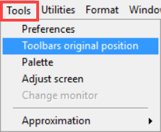
This option in the Tools menu automatically positions all the toolbars in their original default position. However, it only relocates the toolbars that are visible.
12.3.Palette
This option allows you to define and save different color palettes.
These palettes are made up of 256 colors defined from among 16 million possibilities. The color system is RGB.
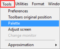
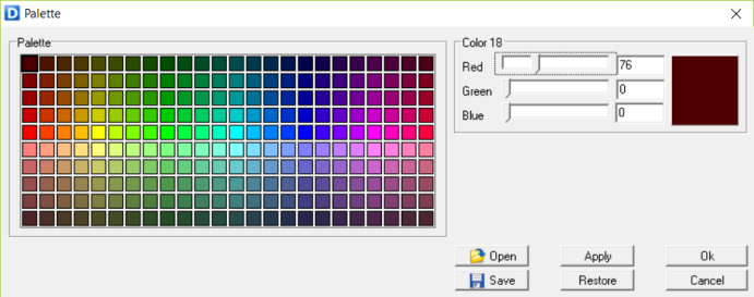
12.4.Adjust screen
In this menu, you can indicate a scale factor that puts the drawing on the screen at the real scale, regardless of your monitor size.
To do this, you need a ruler or a hand scale.
 Draw a square 10 x 10 cm. (0.1 m.)
 Centre the drawing with F3 (extended zoom)
 In the scale box, select 1/1
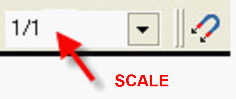
 Measure one side of the square with the ruler.
 Divide the on-screen measurement in centimeters by 10 cm (current dimension/desired dimension).
 Enter the result in the [Adjust Screen] window.
12.6.Approximation
The menu that appears in this option is also available in its own toolbar.
When the program starts up, the automatic approximation is activated by default. This activates the first five approximations. This way the cursor snaps to the closest sensitive point of the selected grips (approximations).
These grip points (markers) snap when the cursor is near, and they indicate the place where they will be attached to implement the current function.
There is also a dialog box that can be activated at any moment and from any function by pressing: CTRL + RIGHT CLICK.
The color of the grip points (markers) can be changed in the following menu: [Tools] – [Preferences] – [Color] – [Markers].
13.1.Activate / Deactivate
This option is very important because it allows you to hide similar items without using the layers, thus saving time when working on a project.
Dibac recognizes any element drawn or inserted in the project.
These elements are the ones that appear in the adjoining screenshot:
Regardless of the layer in which these items might be found, when these items are unchecked they are no longer visible on the screen, even though they continue to exist in the drawing.
The select, move, erase, etc. functions do not affect deactivated items.
To see the items again, just activate them.
13.2.Selection
13.2.1.Selection by attributes / objects
This function is under [Utilities] – [Selection] – [Selection by attributes/objects].
This function allows you to select all the items with similar attributes. This way you can select objects in the drawing with the same characteristics.
You can make the selection by:
-
Layers. The [Layers] option lets you select items found within one layer or more.
-
Colors. The [Colors] option lets you select the items that have a specific color, choosing from a color palette that appears subsequently.
-
Items. The [Items] option lets you select the objects in the drawing with the same definition, including items that have a specific characteristic or dimension. You can choose from different drop-down menus and expand to specify.
-
Line Thickness. The [Line thickness] option lets you select items in the drawing with a specific line thickness, choosing from the thicknesses used in your drawing, which appear on a drop-down palette in the menu
-
Line type. The [Line type] option lets you select the items from the drawing with a specific line type, choosing from the palette that appears subsequently.
Within each of these options, you can specify the characteristics and attributes of an element by clicking the drop-down icon. This way you can make a more accurate selection.
To select additional attributes for the final selection, click on the items by pressing the CTRL key 
For example, you can select all the doors that are blue and 0.725 meters, in the entire drawing or just those in an area of it.
The type of line of the items selected will change, and the grips with which you selected them can be moved and will be shown.
Once you have finished selecting, you can do whatever you want with it: change the attributes of color, line or layer, copy, make symmetrical, delete, etc
13.2.2.Individual selection
With this function, you can select element by element, individually, or by defining an area by moving the cursor and holding down the left button. You can select complete items if you move the cursor from left to right. If you move from right to left, you will select all the elements that have an end or their origin, in case of texts, objects or polygons, within the selection box
The type of line of the items selected will change, and the grips by which what is selected can be moved and will be shown.
13.2.3.Inverted selection (Shift + Selection)
13.2.4.Selection by polygons
Use this function to create a selection of items by an irregular polygon.
 Deactivate H/V ORTO
 Specify the polygon vertices one by one
 To finish, right-click to indicate the last vertex
The function will select all items included inside the polygon.
13.3.Bring to front
13.4.Send to back
13.5.Layers
You have the same options as the [Layers Toolbar]
13.6.Distribute items in layers
In Dibac you can work at a professional level with very few layers. However, when a drawing in DWG is opened in another CAD software, creating layers for each of the items in the drawing can be of interest.
With this tool, you can distribute all items in the drawing from a selection in different layers, depending on the type of object or element. For example, the doors selected can be relocated in a layer named [Doors], the pillars to another layer named [Pillars] and so on.
The new layers, depending on the type of element they are going to contain, will have different names as indicated below:
-
Doors
-
Windows
-
Arc Windows
-
Wardrobes
-
Users Joineries
-
Pillars
-
Block
-
Straight walls
-
Curved walls
-
Lines
-
Arcs
-
Circles
-
Ellipses
-
Polygons
-
Polylines
-
Multi-point curves
-
Hatching
-
Rectangles
-
Points
-
Texts
-
Dimensions
-
Images
To avoid creating too many or repeated layers, if there is already a layer with one of the names defined previously, this layer will be used. Consequently, you can select different areas of the drawing without duplicating layers.
13.7.Open holes in hatches
This function allows you to make holes in the hatches permanently in order to open the DWG files in other programs, which do not have the possibility of covering the hatches with the objects superimposed onto them.
13.9.Convert to 2D
This function changes the DWG planes in 3D into 2D. It is particularly useful in Elevation Plans.
13.10.Block attributes
This function allows you to move the image of blocks to Layer 0. This block transfer is done individually or in groups, according to the blocks selected. You can also select them all.
When you move the blocks, you can keep or change color or line type attributes according to the adjoining screenshot:
-
Do not modify
-
By layer
-
By block
-
Fixed color / Fixed Line Type
13.11.Hyperlink
The Hyperlink function allows you to assign a hyperlink or an URL to any object of the drawing.
The hyperlink can launch any installed processing software by assigning to the hyperlink the corresponding path of a specific file saved in our local disk. For example, if we assign to the Hyperlink the directory path of a SketchUp file, Dibac CAD will launch SketchUp and will open that file.
Besides opening any stored file in our hard drive, the hyperlink function can also open the web browser if we associate a website URL.
To associate a hyperlink to an object you need to follow these steps:
 Click on the Hyperlink icon
  under the Standard toolbar or in the “Utilities” dropdown menu.
 Type or paste the hyperlink. If you want to associate a file, make sure you insert the file path correctly. For example, C:\Users\USERNAME\Desktop\DIBAC_CAD\Projectfile.dwg
 Press Ok.
 Select the object in the drawing (block, text, line, wall, etc…)
Once the hyperlink is associated to the object, a “blocked hand” symbol will appear when you hover the pointer in selection mode over the object. This is means that the object has a hyperlink but its blocked.
To launch it you must press and hold the  key while clicking on the object.
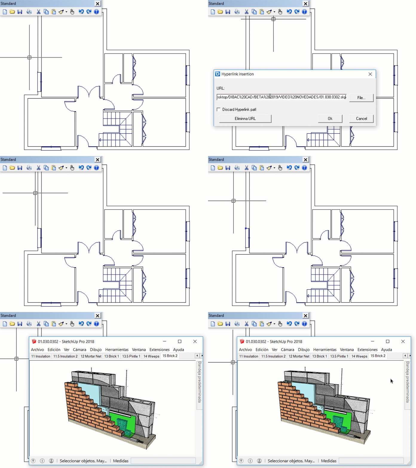
Discard path
This option can be activated when the associated file is saved in the same folder as the project file of Dibac CAD. This is very useful when sharing the project with someone else and adjoining all the associated files in the same folder.
13.12.Convert to fixed color
This function serves to change the color of the Layer option for different layers in the drawing to its color, but with the name of each color itself.
It is very practical when, for example, you receive a file with layer colors chosen by its author and you want to change those colors to those that you usually use. The first step is to set the different layer colors to each color. The second step is to change those colors to yours.
13.13.Convert to fixed line type
This function serves to change the Layer line type in exactly the same way as indicated above for layer color.
13.14.Coordinates in polyline vertexes
Commands: “VERTIPOLY” “VP”
Use this function to place the coordinates list of the polyline vertexes in the drawing.
 From the Utilities menu, select the function Polylines vertexes
 Click on the polyline
 Click where you desire to see the Text column with the coordinate list of the polyline
The multiline text will have the coordinates of every polyline vertexes.
13.15.Zoom factor
13.16.Polar tracking
The polar tracking function restricts or snaps the movement of the cursor to the specified polar angle defined in the polar tracking angle window.
This function is under the [Utilities] menu.
You can choose between three options:
-
Polar tracking angle. You can specify the polar angle increments in the pop-up window.
-
Enable polar tracking. You can enable or disable the Polar Tracking.
-
Polar tracking lock. If this option is enabled, the cursor will be restricted only in the angle increments of the specified polar angle. If this option is disabled, the cursor will move freely but the polar tracking will snap in every increment of the specified angle.
13.17.Screen coordinates
When you activate this option, the coordinates of the cursor appear on the bottom left-hand side of the screen.
If you need coordinates while drawing, use the following process to enter them:
13.18.Editable commands
We can easily change the commands of the tools and functions of the program. For example, the command for ARC is AC, LINE is LI, etc. These abbreviated commands can be entered in the command bar to activate a drawing tool faster.
In the Utilities menu, the option called “Commands” allows you to modify the abbreviated commands. A dialog box will appear with a list of the commands and their corresponding shortcuts. Only these commands can be modified.
14.Layers Toolbar
Commands: “CAPA”,”CA”
14.1.Layers
The layer is the common place where several items in the drawing belong. This function allows you to define and modify the characteristics of these layers.
After clicking the layers icon, a dialogue box will appear, and the current layer will be indicated in the upper left-hand part. Everything that has been drawn will belong to this layer by default.
NOTE. Besides the layer window, you can select the current layer by opening the layer drop-down bar in the Properties toolbar. Dropping down this bar allows you to change the Current layer by selecting one of the layers.
To make a layer “Current” in the Layer window, just select one of the layers and then click on the [Current] option. A green check mark will appear on its left revealing that it’s the new current layer, in which you will continue drawing.
14.1.1.Options in the Layers window
Inside the Layers Window, you will find the following options:
-
Select all. Clicking on this option selects all the layers
-
Deselect all. By clicking on this option, all layers remain unselected.
-
New Layer. To create a new layer, enter its name on the right-hand side and then press [New Layer]. The new layer should now appear on the list, organized in alphabetical order, but never as a current layer. If you press [New] without entering a name beforehand, Dibac will create a layer by default, with the name LAYER1, LAYER2, etc.
-
Delete. All selected and deleted layers that do not contain any items will be deleted.
14.1.2.Columns in the Layers Window
The options of the columns icons are:
Status
It shows the current layer. By double clicking on the page symbol, you can change the current layer.
Name
It refers to the name of the layer. To change the name, double click on it. Press Yes twice.
On
It is the layer’s switch. It is recommended to keep it activated always.
Freeze
 Sun icon
  Snow icon
The column called FREEZE turns the layers in the drawing on and off.
The items in the hidden layers (snow) will not be visible on the screen and will not be affected by any program function.
You can use this function directly from the Layers drop-down bar in the Properties toolbar
If the SUN of one or more layers is turned on, the items in these layers will be visible on the screen and will be affected by all the functions of the program, this being the normal status of the drawing.
If you select all the layers and deactivate them by pressing the SUN icon, the current layer will remain active.
This procedure allows you to see the items belonging to a single layer.
Lock
Use this option to lock or unlock the layers.
The lock option is used to make the items in the selected layers visible with the color of the Locked Layer selected in [Tools] – [Preferences] – [Colors]. The geometry assigned to a locked layer is visible in the drawing but will not be affected by the selection or deletion tools. However, it can be used to interact with the grips and the drawing tools. For example, you would be able to approximate the endpoints of a straight line, make an offset, etc.
-
Locked layer

You can prevent objects in specified layers from being selected and modified by locking those layers.
When a layer is locked, none of the objects on that layer can be modified until you unlock the layer. Locking layers reduces the possibility of modifying objects accidentally.
Objects on locked layers appear faded with the color assigned in [Tools] – [Preferences] – [Colors].
With this function you can reduce the visual complexity of a drawing and it will not be affected by most of the functions, however, it still maintains visual reference and the approximation snapping capabilities of those objects.
-
Unlocked layer

This allows you to unlock the locked layers that you select.
Plot
By pressing the printer icon, you can select which layers you want to print, without deactivating the layers that you do not want to print.
Color
This allows you to assign a specific color to one or more selected layers. This color will be the layer color that appears on the color list.
You can choose the color of a layer directly by clicking on the square of color that appears on its line.
Line type
This allows you to assign a line type to one or more selected layers. This line type will be the one that is applied with the name of the layer.
You can choose the line type of a layer directly by clicking on the rectangle in which the name of the line type appears.
Line thickness
The line thickness option is used to select the line thickness for a layer.
You can choose the thickness used in a layer directly by clicking on the rectangle in which the line thickness appears.
Deactivate a layer in a presentation window
You can deactivate specific layers in any of the different presentation windows.
Starting in a presentation just enter the drawing window by double-clicking and, in the drop down layers menu, deactivate those layers you do not want to include.
In a presentation window, layers that are previously deactivated in the “Model” will not be activated.
14.2.Capture layer
Commands: “CAPTARCAPA”, “CC”
This function allows you to know the layer of a specific item in the drawing, as long as this item is active and belongs to an active layer.
Just enable the function, click on any item you of the drawing, and the layer name will appear in the layer drop-down bar.
Furthermore, this layer will be set as the current layer, so all items drawn after that moment will be drawn on this layer.
14.3.Change layer name
14.4.Delete layers
14.5.Copy layers
14.6.Layer manager
In this window, you can create groups of layers and indicate their status.
In the groups, you can include the activated, deactivated and locked and unlocked layers.
These groups are created automatically when you define the presentations. The layer group will have the same name as the presentation.
You can also make new groups in a random manner.
15.1.Arbitrary
With this option, you can place guides anywhere you want in the drawing.
If an approximation is active, the cursor will snap on the grip and you can place the guide on it. For example, if you enable the circle center approximation beforehand, you will be able to place the guide in the center of the circle.
15.2.Distance
With this option, you can place a guide at a certain distance from a given point.
This guide will follow a direction, be it a straight line or a perpendicular one.
 Once this function is selected, first enter the distance and then press Enter.
 Next, click on the first point (origin) and then the direction in which you want to place the guide at a distance.
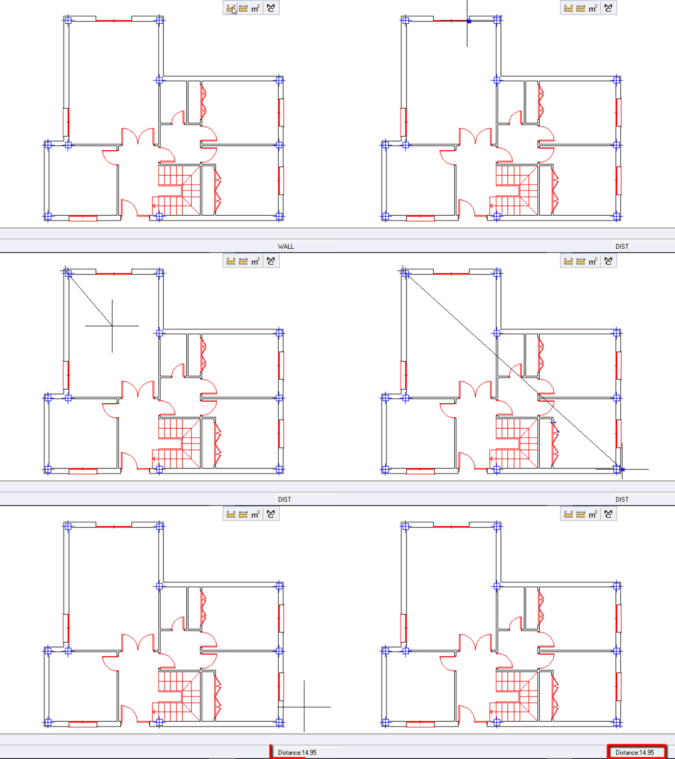
15.3.Intersection
15.4.Equal parts
15.5.Maximum distance
15.6.Triangulation
This function is used primarily to set up buildings and plots.
When you enter the function, a square appears in which you can enter two radius values.
Once you have entered these values, select the two points, keeping in mind that the intersection of these circles will be drawn to the left of the direction in which the points are marked, that is, on the positive side.
Example
16.1.Text style
This allows you to define the fonts of the texts to be inserted or those that have been already placed in the drawing.
When you select this function, a dialogue box appears.
 To create a new text style, press [NEW].
 Another dialogue box appears in which you should enter the name of the new style and then press [Ok].
 Select the newly created style in the [Name] box.
 Configure whichever text parameters you want: Font, Size, Bold, etc.
(The Upside down and Left mirror reflection effects refer to the vertical and horizontal symmetries of the text)
 Click [Ok]
The created style is saved in the drawing itself.
16.2.Dimension style
16.3.Point style
16.4.Scale line type
Command: “ETL”
Some of the line types that the program comes with can be scaled. This means, for example, that the spaces of a dashed line can be lengthened or shortened
To do this:
 Enter the menu: Format – Scale line type
16.5.Grid
This function allows you to create a mesh of points (grid) with a specific horizontal and vertical density.
You can define a grid with point spacing and limits that determine a specific area.
The advantage of using grids is that it serves as a base upon which you can draw more comfortably, like graph paper.
-
The defined grid always appears when you press the F7 key.
-
It also disappears when you press F7 again.
17.1.Close
This closes the current window, asking if you want to save it beforehand.
17.2.Close all
This closes all the windows at the same time, asking first if you want to save them
17.3.Cascade
This presents all the open windows in the form of a cascade
17.4.Horizontal display
This presents all the open windows in horizontal mosaic.
17.5.Vertical display
This presents all the open windows in vertical mosaic.
17.6.Arrange icons
If you have several drawings open and you minimize them you can use this function to place them on the bottom-left-hand side of the screen.
You can move these icons across the screen, changing their original position.
Use function Arrange icons to replace the icons in their original position, on the bottom left-hand side of the screen.
18.1.Color
This menu option allows you to define the color of any new item to be placed in the drawing. You can also change the color of something already drawn after being selected.
When you click on this arrow, a dialog box opens with Layer and Block colors, 7 basic colors, color 255 and a box labeled [Other].
Layer color
The layer color will be the color activated in the current layer. Consequently, if you change to another layer that has a different color defined, the layer color will be different.
Block color
The block color is the color that should be used when drawing the geometry of blocks.
This way, the block created with the block color can be placed on the drawing in any color you want.
If a block is created with other colors different from the block color, it will always be inserted in its true colors
Other
If you click on [Other], a dialog box with all the possible colors opens.
18.2.Line type
This menu option allows you to define the line type for anything new that you draw. You can also change the line type of something already drawn, as long as it was previously selected.
When you click on the arrow, a drop-down menu opens showing the Layer, Block and Continuous line types, as well as a box labeled Other.
If you click on Other, a dialog box with all the possible line types opens.
18.3.Line thickness
You can use this option to change the thickness of the line you are going to draw, or existing lines that have previously been selected.
The same type of line can be drawn with different thicknesses, as thickness is an attribute separate from line type.
The value of 0.00 places the line with its default thickness.
Thickness is measured in centimeters, so 0.03 would be 3 tenths of a mm. and 0.1 would be 1mm

