Overview
Download
User Manual
Videotutorials
Pricing
Resellers
Support
Buy now
1.WALLS
These are all the functions available for the ‘Wall’ tool:
1.1.Wall thickness
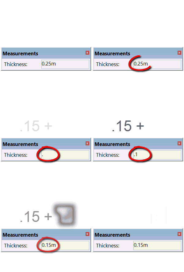
Once the WALL tool has been selected ![]() , you will see that you can introduce the measurement for the THICKNESS of the wall in the SketchUp box of values.
, you will see that you can introduce the measurement for the THICKNESS of the wall in the SketchUp box of values.
To change its thickness, simply type in the desired measurement and press the ENTER key to confirm.
1.2.How to draw a wall
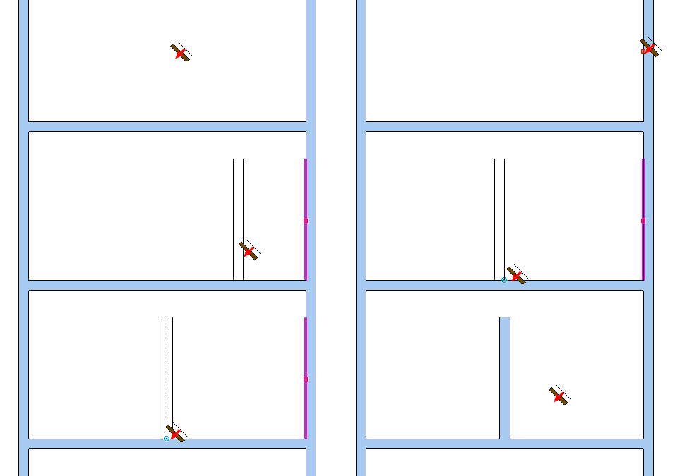
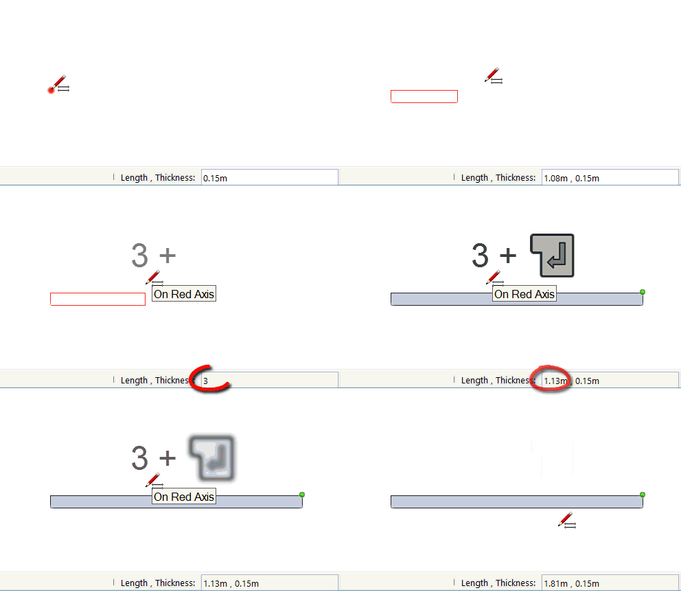
Once the WALL tool has been selected and the THICKNESS changed, click wherever you want to start drawing the wall. Indicate this by moving the mouse in that direction, type in the length and confirm with the ENTER key.
As well as typing the LENGTH you can change the THICKNESS at the same time depending on how you want your wall to be.
Once you are creating the wall you can type LENGTH; THICKNESS and confirm with the ENTER key.
Once the first wall is complete, the cursor should remain attached to its top corner indicated by a colored dot. When you finish creating walls, press ESCAPE in order to detach it.
1.3.Changing the attachment point
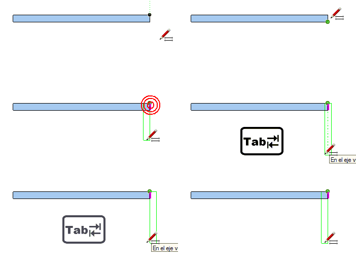
To change the attachment point, press the TAB button repeatedly until the desired point is reached.
1.4.Blocking inferences
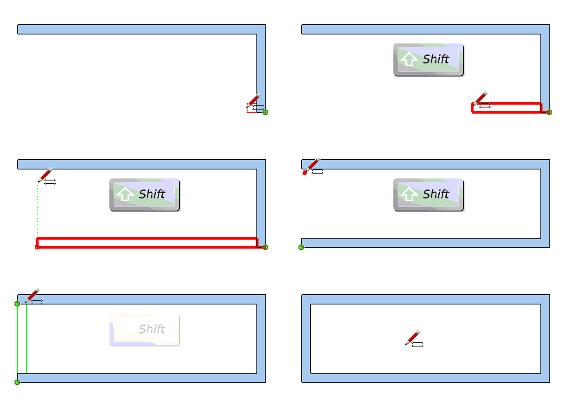
Like SketchUp, when we are creating a wall, we can block its direction by holding down the SHIFT key.
Once it is blocked on an axe with SHIFT, we can align the wall in relation to other points of the drawing and confirm by clicking.
1.5.Deleting a wall
1.6.Drawing a wall with a determined angle
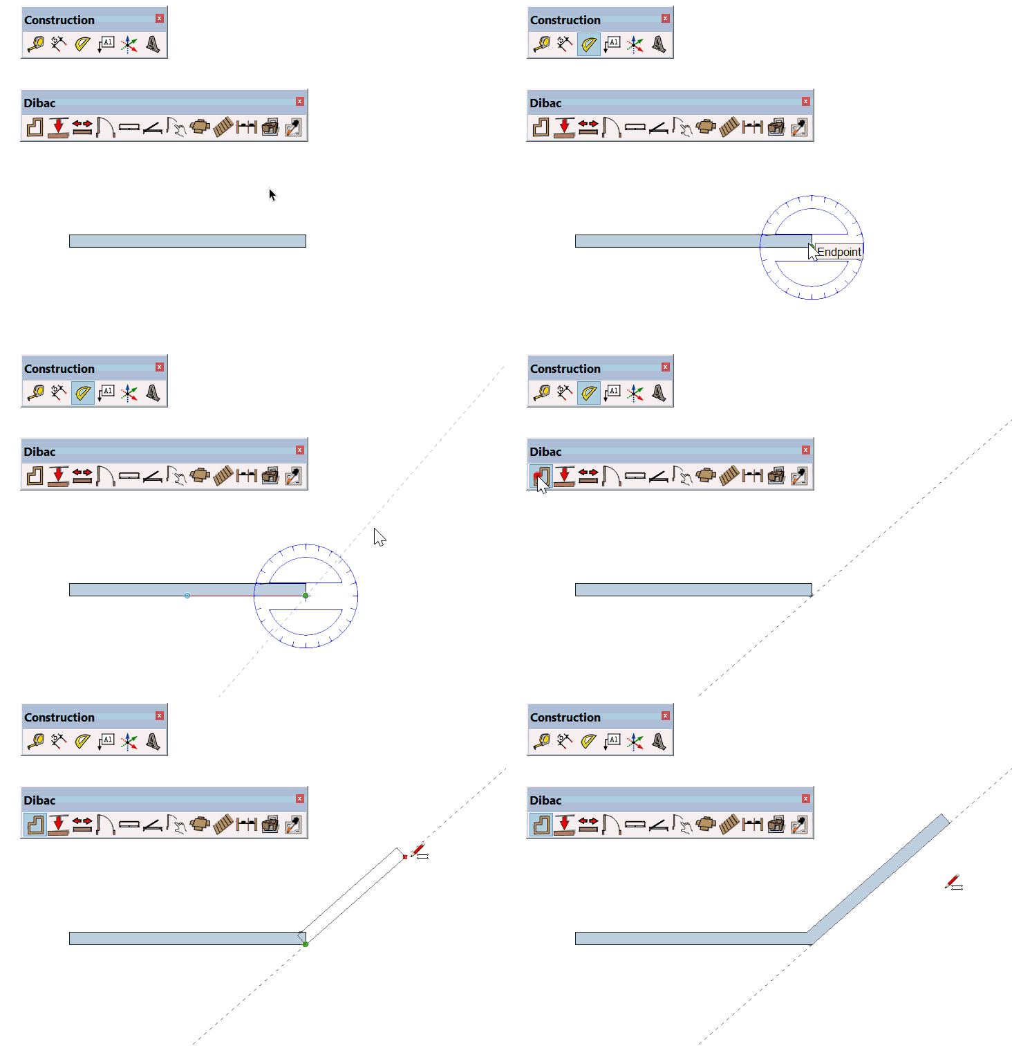
To draw a wall which is not orthogonal and which has a defined angle, we first have to create an auxiliary line with the SketchUp PROTACTOR tool.
2.PARALLEL WALLS

These are the options available for the ‘Parallel Wall‘ tool:
2.1.Parallel wall thickness
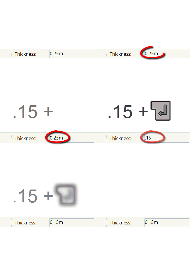
Once the PARALLEL WALL tool has been selected, the THICKNESS of the wall that we are going to create appears in the box of values.
To change the thickness of the wall, type in the desired measurement and confirm with the ENTER key.
2.2.How to draw a parallel wall
Once the PARALLEL WALL tool has been selected and the THICKNESS has been changed, click on the interior/exterior edge of the wall (we would click on the interior edge when the parallel wall goes inwards and on the exterior edge when the wall goes outwards), move the mouse in the direction that the new wall will go, type in the distance and confirm with the ENTER key.
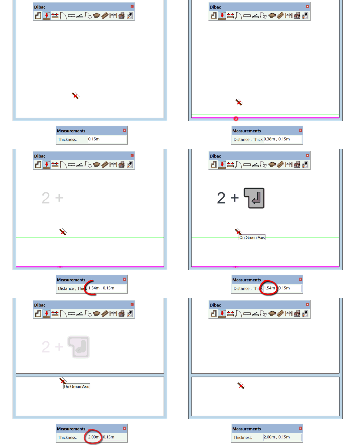
As well as typing the distance between walls, you can change the THICKNESS of the new wall at the same time. Simply type DISTANCE; THICKNESS and confirm with the ENTER key.
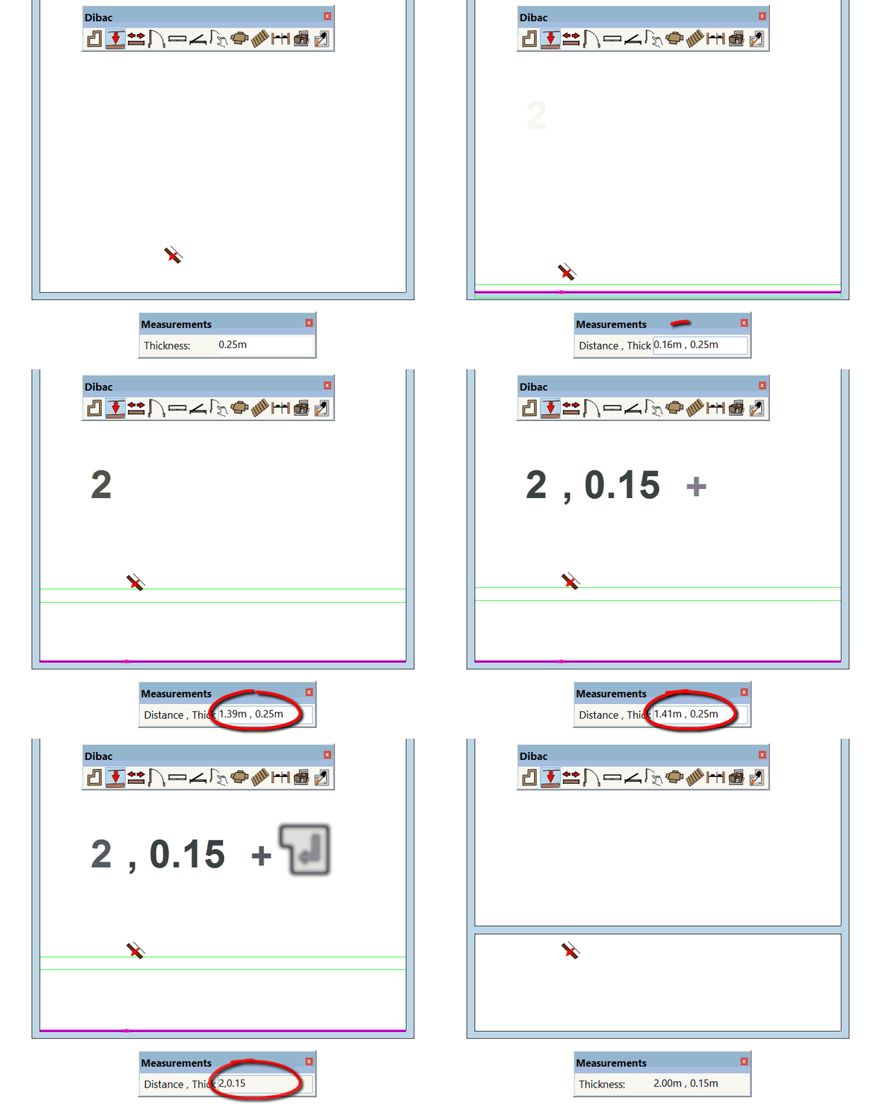
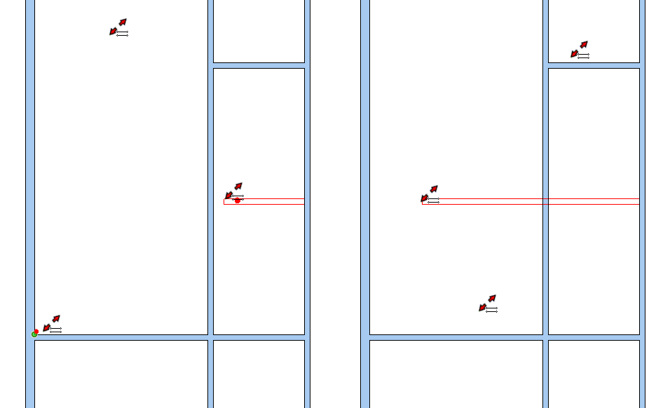
2.3.Changing the attachment point (distance between walls)
2.4.Repeating the previous parallel wall
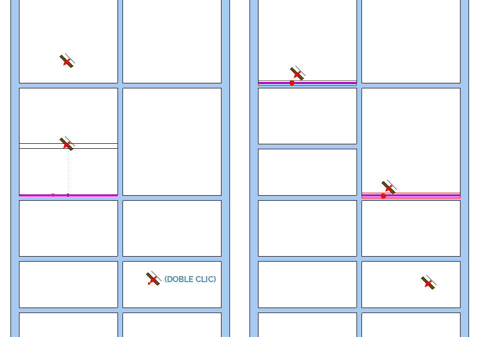
Once you have created the first parallel wall with a determined distance, to create one with the same distance, click on the wall from which you want to start from and, as you are indicating the direction with the cursor, double click. The second parallel wall will be made at the same distance as the previous one.
This action can be repeated with more parallel walls.
3.EXTENDING WALLS

These are all the functions available for the Extend Wall tool:
3.1.How does Extend Wall work?
4.DOORS
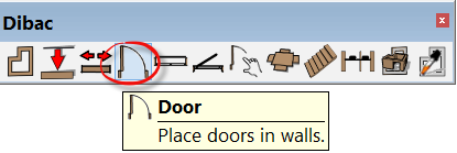
These are the options available for the Door tool
4.1.Door settings
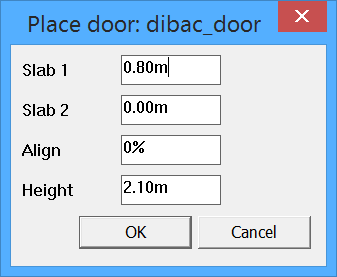
Dibac doors are dynamic components that allow doors of any measurement to be created with the configuration of the following options:
Panel 1: The measurement of the width of the first panel.
Panel 2: The measurement of the width of the second panel. We will only use this measurement if we want a double door. If the door has only one panel, this value must be 0.
Alignment: Indicates the percentage of the placement on the width of the wall. If the value is 0% the door will be interior. If the value that we indicate is 100%, the door will be placed on the exterior of the wall. A value of 50% will place the door in the center of the thickness of the wall.
Height: The measurement of the height of the door.

4.2.Insertion points (endpoint and central)
Once we have accepted the different parameters of the door, the cursor will show a preview of it.
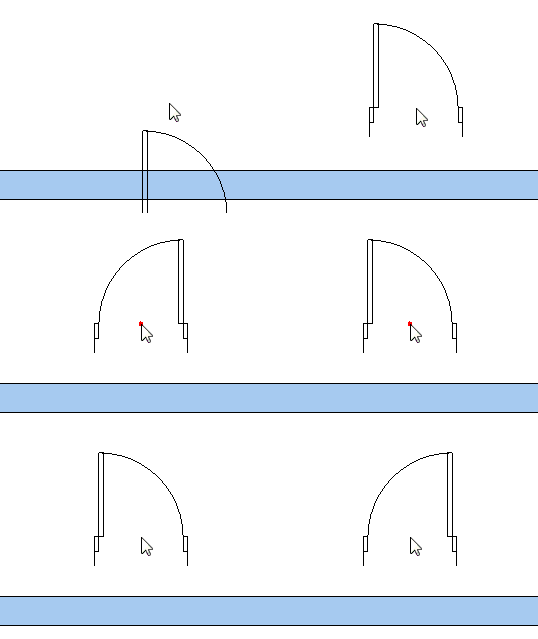
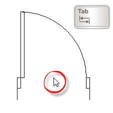
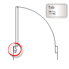
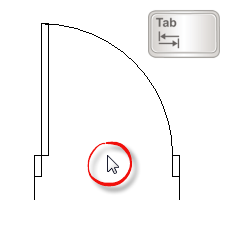
There are two possible insertion points: Endpoint and Central. To change from one point to another we press the TAB key.
- Endpoint: The insertion point will be on one of the lateral vertexes of the door.
- Central point: The insertion point will be in the center of the door.
4.3.Placement of doors
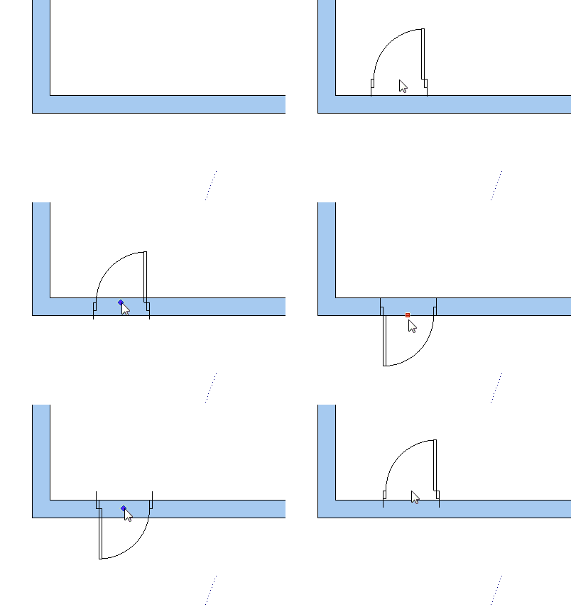
Free placement:
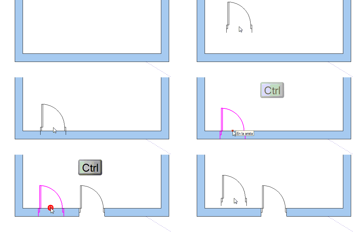
Once we have accepted the parameters of the door, move it towards the wall, wait for it to turn magenta and click to place it where we want it. Provided that it is magenta, we will be able to place the door.
Centered in the wall:
To place a door in the center of the wall, it is first necessary to have the insertion point in the center (press the TAB key to change the insertion point).
When we approach the wall to place the door and the door becomes magenta, press the CONTROL key and we can see that the door becomes blocked in the center of the wall. Click to confirm.
4.4.Elevation and forcing a distance
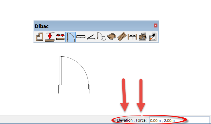
Observe that below, in the SketchUp measurements box we can introduce two values: ELEVATION; FORCE.
ELEVATION: The distance of the entire door in relation to the ground (By defect 0) (Not to be confused with the height of the door in its initial parameters)
FORCE: Force the door to a fixed distance from the nearest corner.
PRACTICAL EXAMPLE
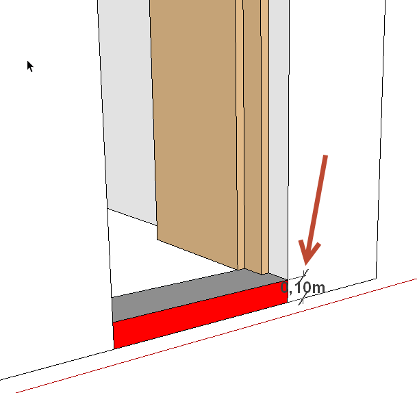
As an example we are going to elevate the door to a height of 10 cm. in relation to the floor and we are also going to force its placement to 30 cm. in relation to the wall:
Select the door tool icon and, before placing it, type the values in directly and confirm with the ENTER key. The format of introduction is (elevation; force), that is to say, we type 0.10; 0.30 and confirm with the ENTER key. You will see that our measurements have been saved in the measurements box.
![]()
Place the door on the side of the wall upon which it will open and, when it becomes magenta, press CTRL (this will force the placement to the chosen measurement). In our case, it will be placed at 30 cm. in relation to the nearest corner. Click to affix it.
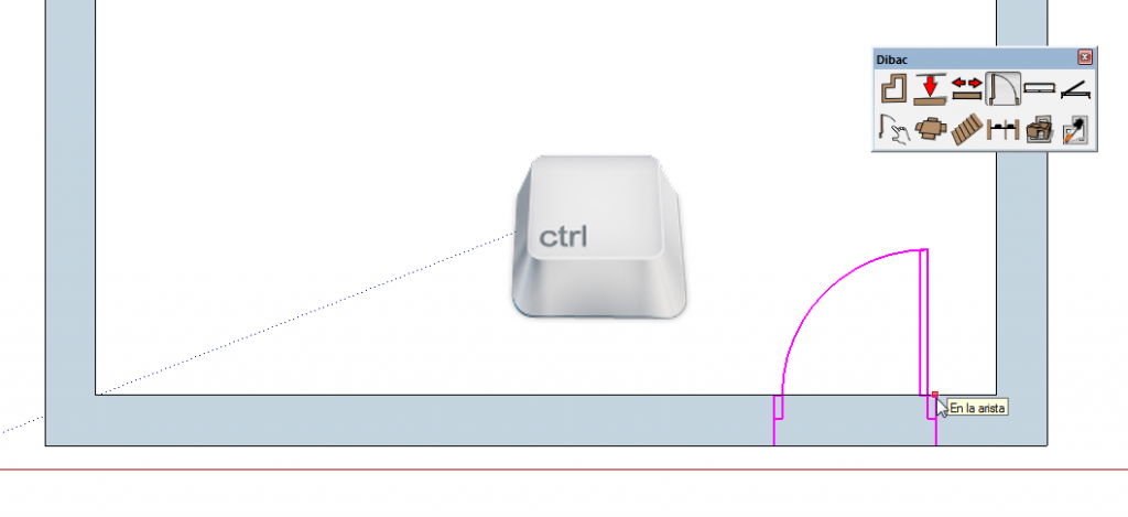
In floor plan the elevation won’t be apparent, but when we construct it in 3D we will see that the door is 10 cm. from the floor.
4.5.Deleting doors or creating openings
Delete a door and reconstruct the wall
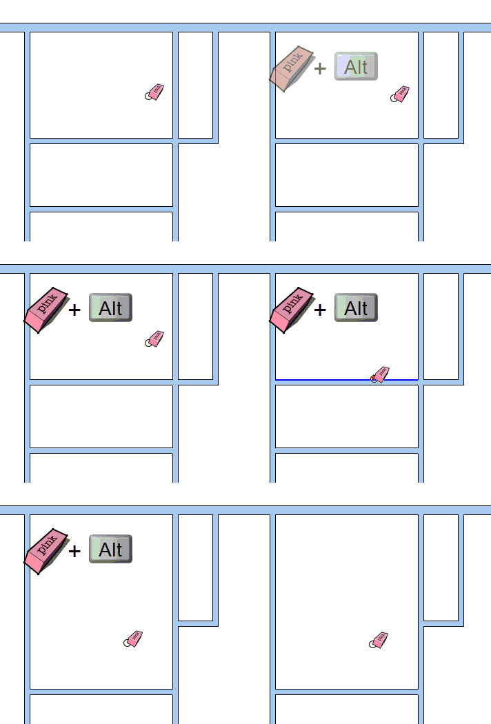
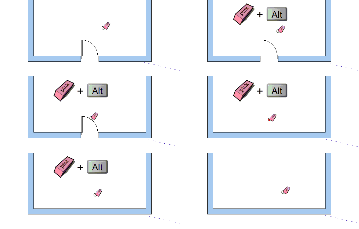
Click on the SketchUp DELETE tool. If you delete whilst moving over the door and pressing the ALT key, the door will be deleted and the wall will be reconstructed.
Create an opening
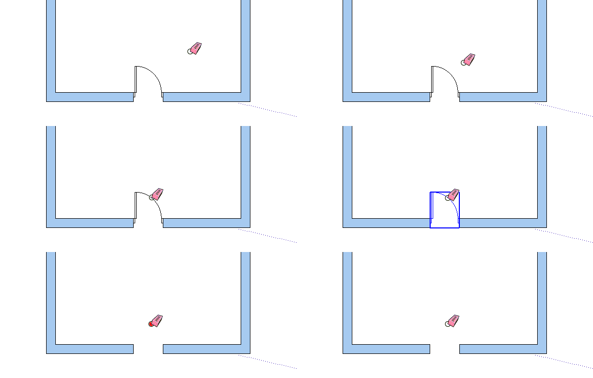
Place a door in the space where you want the opening and simply delete the door to create the opening.
You can do this with the SketchUp DELETE tool or with the DEL key of the keyboard (first select the door that you want to delete). The door will be deleted and will leave an opening in the space where it used to be.
4.6.Substituting one door for another
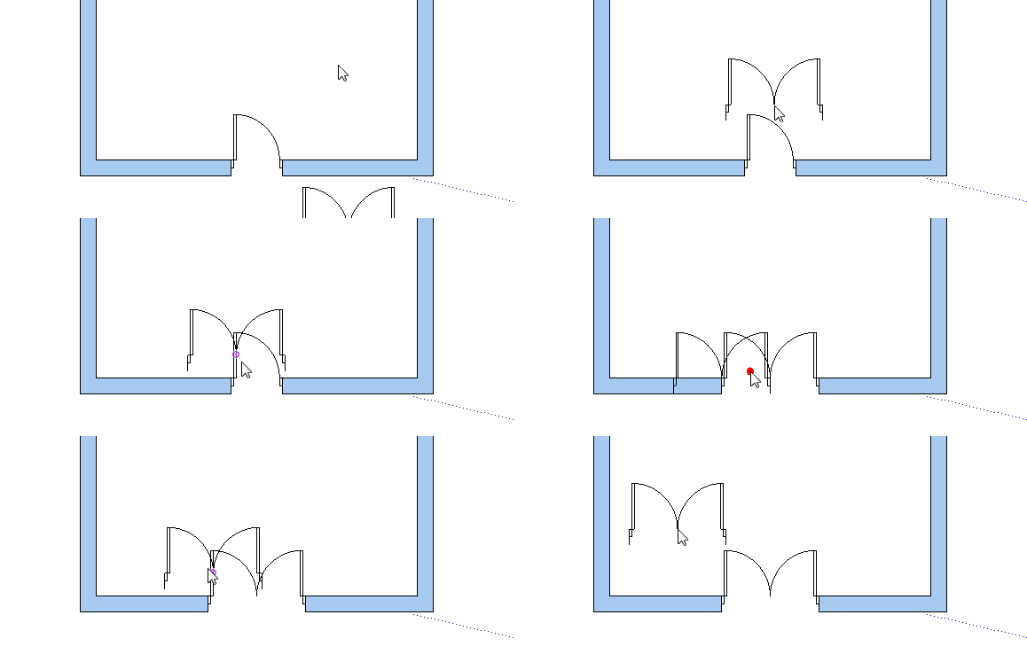
To place a new door, with different measurements, in the same place where there is already a door, simply click on the DOORS tool, select the new measurements, and position the cursor over the existing door. It will turn magenta, click to confirm the placement and the existing door will be replaced by the new one.
5.WINDOWS

These are the options available for the Window tool:
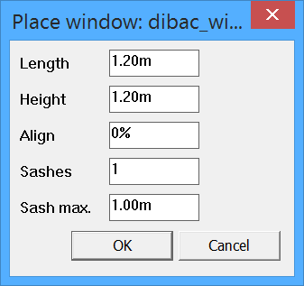
5.1.Window settings
Dibac windows are dynamic components that allow windows of any measurement to be created with the configuration of the following options:
- Length: The measurement of the width of the window.
- Height: The measurement of the height of the window.
- Alignment: Indicates the percentage of the placement on the width of the wall. If the value is 0% the window will be interior. If the value that we indicate is 100%, the window will be placed on the exterior of the wall. A value of 50% will place the window in the center of the thickness of the wall.
- Panels: The number of panels that the window will have.
- Maximum panel measurements: The maximum width of the panel. That is to say, panels with a value larger than the one that we provide will never be created. As many panels with a width inferior to this value that can possibly fit will be automatically placed, depending on the length of the window.
5.2.Insertion points (endpoint and central)
Once we have accepted the different parameters of the window, the cursor will show a preview of it.
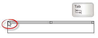
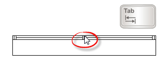
There are two possible insertion points: Endpoint and central. To change from one point to another we press the TAB key.

Endpoint:
The insertion point will be on one of the lateral vertexes of the window.
Central point:
The insertion point will be in the center of the window.
5.3.Placement of windows
Free placement:
Once we have accepted the parameters of the window, move it towards the wall, wait for it to turn magenta and click to place it where we want it. Provided that it is magenta, we will be able to place the window.
Changing the traction point:
ONLY WHEN OUR INSERTION POINT IS ON THE ENDPOINT (press TAB to change this). We can pick up the window from either the right or left side. Simply move the cursor over an empty part of the drawing and click to change the traction point.

Changing the direction of the window:
To position the window on one side or another of the wall simply move the window towards the interior or exterior edge of the wall.

5.4.Elevation and force
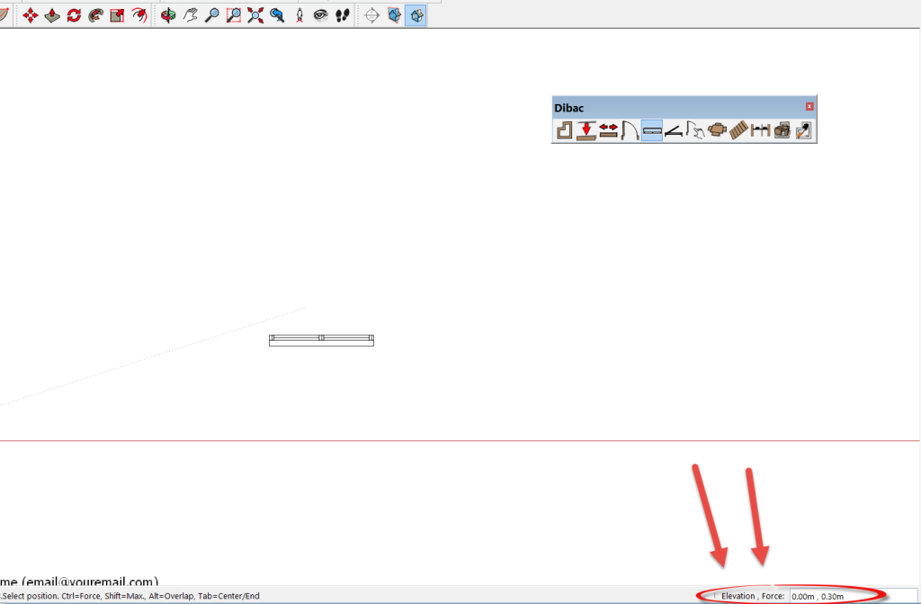
Observe that below, in the SketchUp measurements box we can introduce two values: ELEVATION; FORCE.
ELEVATION: The distance of the entire window in relation to the ground (By defect 0) (Not to be confused with the height of the window in its initial parameters)
FORCE: Force the window to a fixed distance from the nearest corner.
PRACTICAL EXAMPLE
As an example we are going to elevate the window to a height of 120 cm. in relation to the floor and we are also going to force its placement to 30 cm. in relation to the wall.
Select the window tool icon and, before placing of introduction is (elevation; force), that is to say, we type 1.20; 0.30 and confirm with the ENTER key. You will see that our measurements have been saved in the measurements box.
![]()
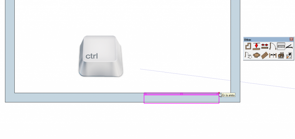
Place the window on the correct side of the wall and, when it becomes magenta, press CTRL (this will force the placement to the chosen measurement). In our case, it will be placed at 30 cm. in relation to the nearest corner. Click to affix it.
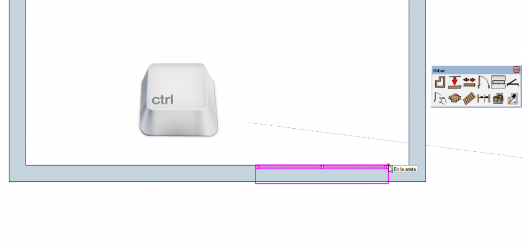
In floor plan the elevation won’t be apparent, but when we construct it in 3D we will see that the window is 120 cm. from the floor.
5.5.Deleting windows
Delete a window and reconstruct the wall
Click on the SketchUp DELETE tool. Keep the ALT key held down and delete the window. You will see that, as well as deleting the window, the wall has been rebuilt.
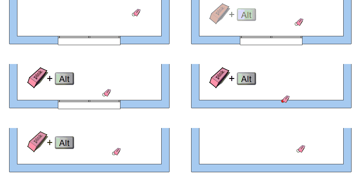
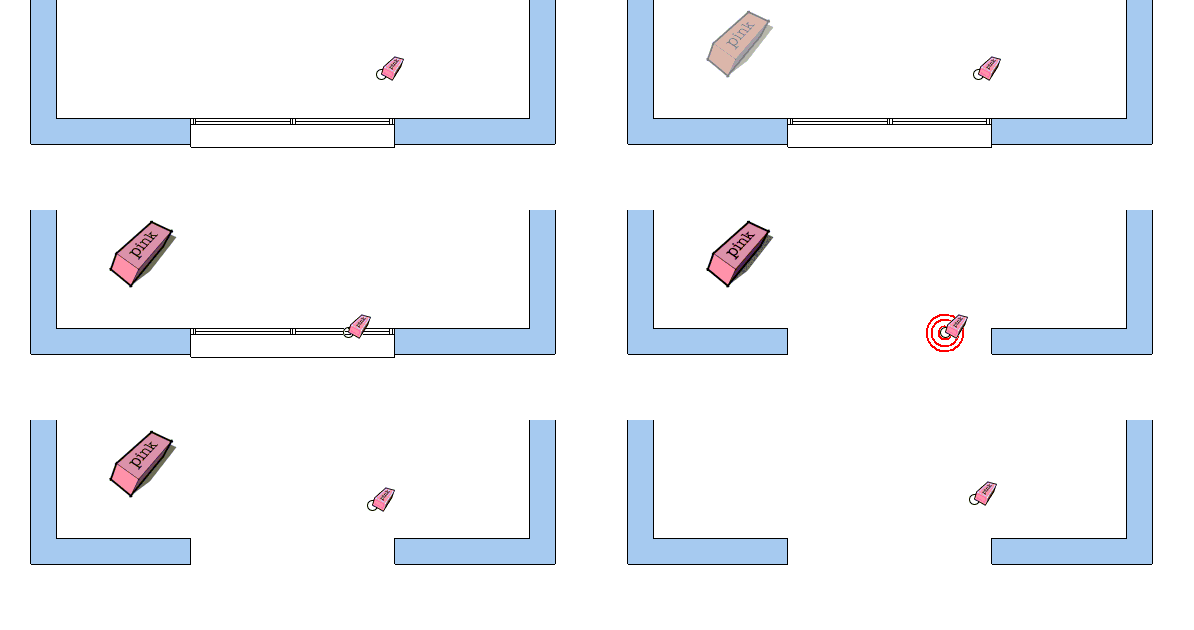
Delete a window and DO NOT reconstruct the wall
You can do this with the SketchUp DELETE tool or with the DEL key of the keyboard (first select the window that you want to delete). The window will be deleted and will leave an opening in the space where it used to be.
5.6.Substituting one window for another
To place a new window, with different measurements, in the same place where there is already a window, simply click on the WINDOWS tool, select the new measurements, and position the cursor over the existing window. It will turn magenta, click to confirm the placement and the existing window will be replaced by the new one.

5.7.Placing a window that covers the measurement of a wall
When placing a window, move towards the desired wall and the window will turn magenta.
Before confirming the placement, hold down the SHIFT key and it will remain magenta but will cover the entire wall. At this point, click to place the window, which will cover the entire length of the wall.

6.SELECTING CUSTOM JOINERY
Any component that is to be placed on a wall (door, window, closet…) is considered joinery. Dibac allows us to use any self-owned joinery which we may have created or downloaded from, for example, 3D Warehouse.
Press the Select Joinery tool and our computer’s browser will open. Search for the component and open it. We will see that the cursor shows us a preview in which a section of the component is shown.
This component has the same functions and properties of any of Dibac’s joinery (door, window, or closet)
If we are faced with a component that has been created with an incorrect covering, we can explode it and recreate it by simply selecting that the geometry of the joinery becomes contained within the component.
If we have downloaded a component from the gallery and the covering is correct but the axes are NOT correctly positioned, we can change them without having to explode the component.
Right click on the component and select the option CHANGE AXES.
6.1.How to create a ‘Dibac Ready' component?
With the choose joinery tool we can place any component on a wall. But in order for everything to function correctly, we must first make sure that the axes of the component are correctly positioned.
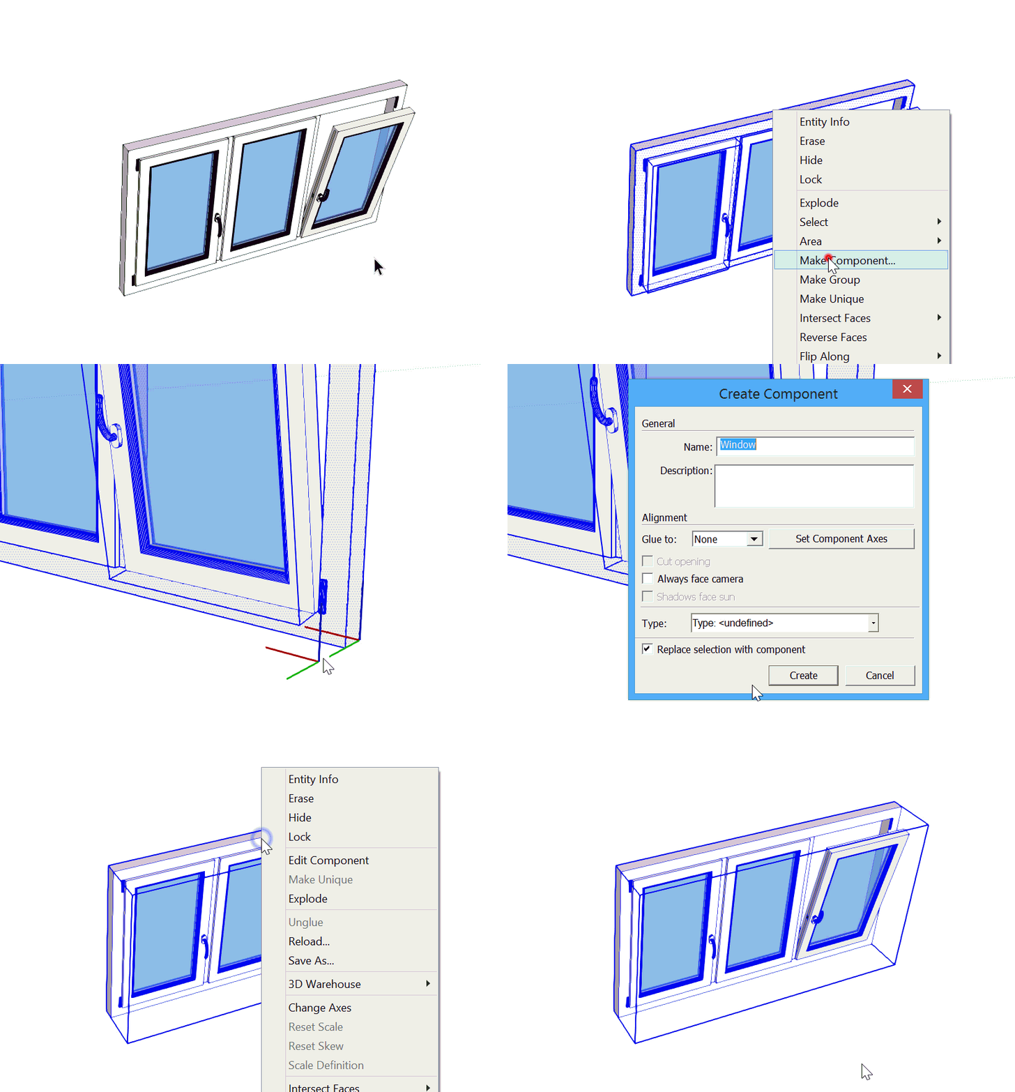
- Open the model that you want to use in a new window of SketchUp. Select the entire model, right click on the selection and select the option CREATE COMPONENT.
- When the window for the creating the component opens, select the option DEFINE AXES OF THE COMPONENT. This is very important
- Now we will position the axes of the component. Click on the rear lower right vertex of the model. Once it is attached, mark the red axe in the direction of the joinery and click. Now mark the green perpendicular axe towards the opposite side of the model and click. Finally, the blue axe will position itself automatically once the green and red ones have been positioned. Once the axes are correctly placed, click on CREATE.
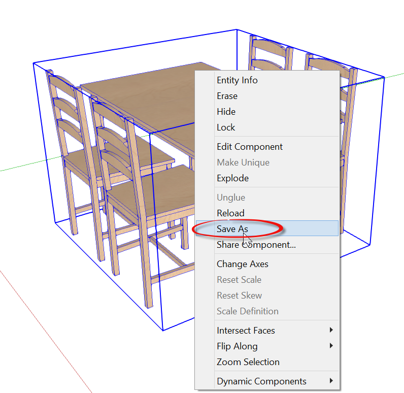
- Finally, save the component on your computer. To do this, right click on the component and select the option SAVE AS.
We now have a component which is fully prepared and ready to be assigned to any wall with the tool SELECT JOINERY.
7.SELF-OWNED COMPONENTS

With the COMPONENTS tool, Dibac allows us to use any of our own components that we may have created or even downloaded from the Trimble 3D GALLERY (furniture, vehicles, vegetation, etc.)
Dibac will automatically make a 2D appearance and also automatically convert it to 3D.
7.1.Downloading a component from the 3D Warehouse
We are going to look at a practical example of how to use a component that has been directly downloaded from the 3D gallery.
![]()
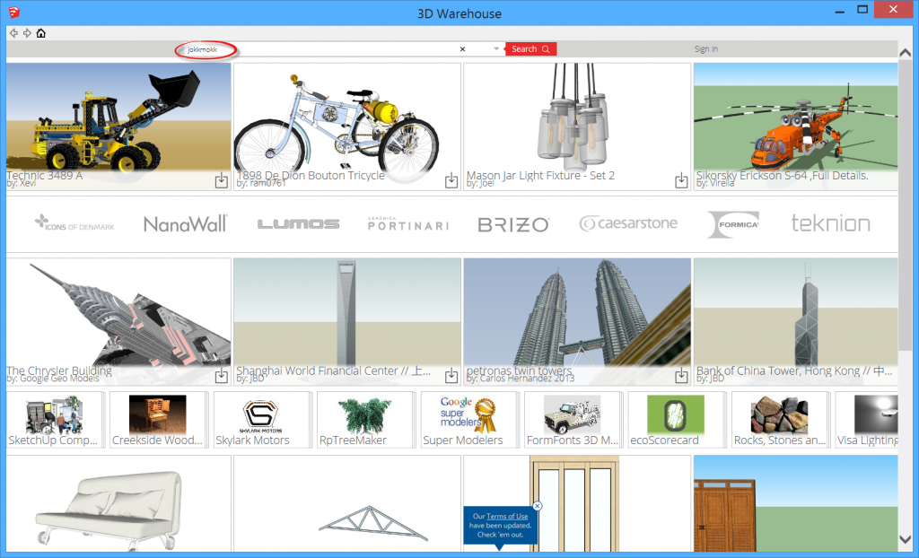
Open the 3D Gallery (archive->3D Warehouse->Obtain models) and in the search bar, type the word JOKKMOKK (A table with chairs by IKEA) and press SEARCH.
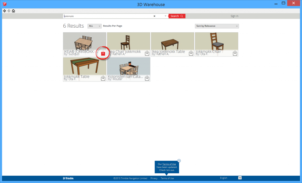
In the obtained results, click DOWNLOAD on the table and chairs that can be seen in the image.
Once we have clicked on DOWNLOAD, we are asked the question: Do you want to download directly to the SketchUp model? If we select YES, it will be downloaded directly into the SketchUp archive that we are working with. If we select NO, it will be downloaded as a new archive.
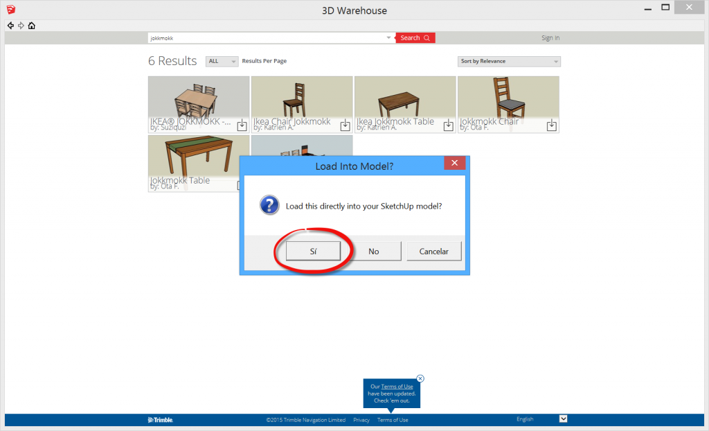
In our case, we will select YES to introduce it into our SketchUp project. Once the component has been downloaded, it will remain attached to the SketchUp MOVER tool. Click to position it in any space.

Now we must correctly position the axes. The placing of the coordinate axes will depend on where we want the insertion point of our component to be.
Right click on the component and select the option CHANGE AXES.
If we want to change them, simply click on the point that we want and click and drag 3 times in order to define the 3 axes (red, green and blue). It is important that the Z axe (blue) remains positive, as this axe marks the direction in which the 3D will be constructed. We must also take into account that the origin of the axes must coincide with the part of the component that is touching the ground.
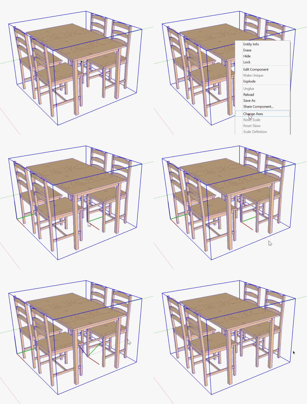
Once the axes are correctly placed, we save the component on our computer. Right click on the component and select SAVE AS. Select the folder where we want to save the component and click on SAVE.
7.2.Placement of a Dibac component
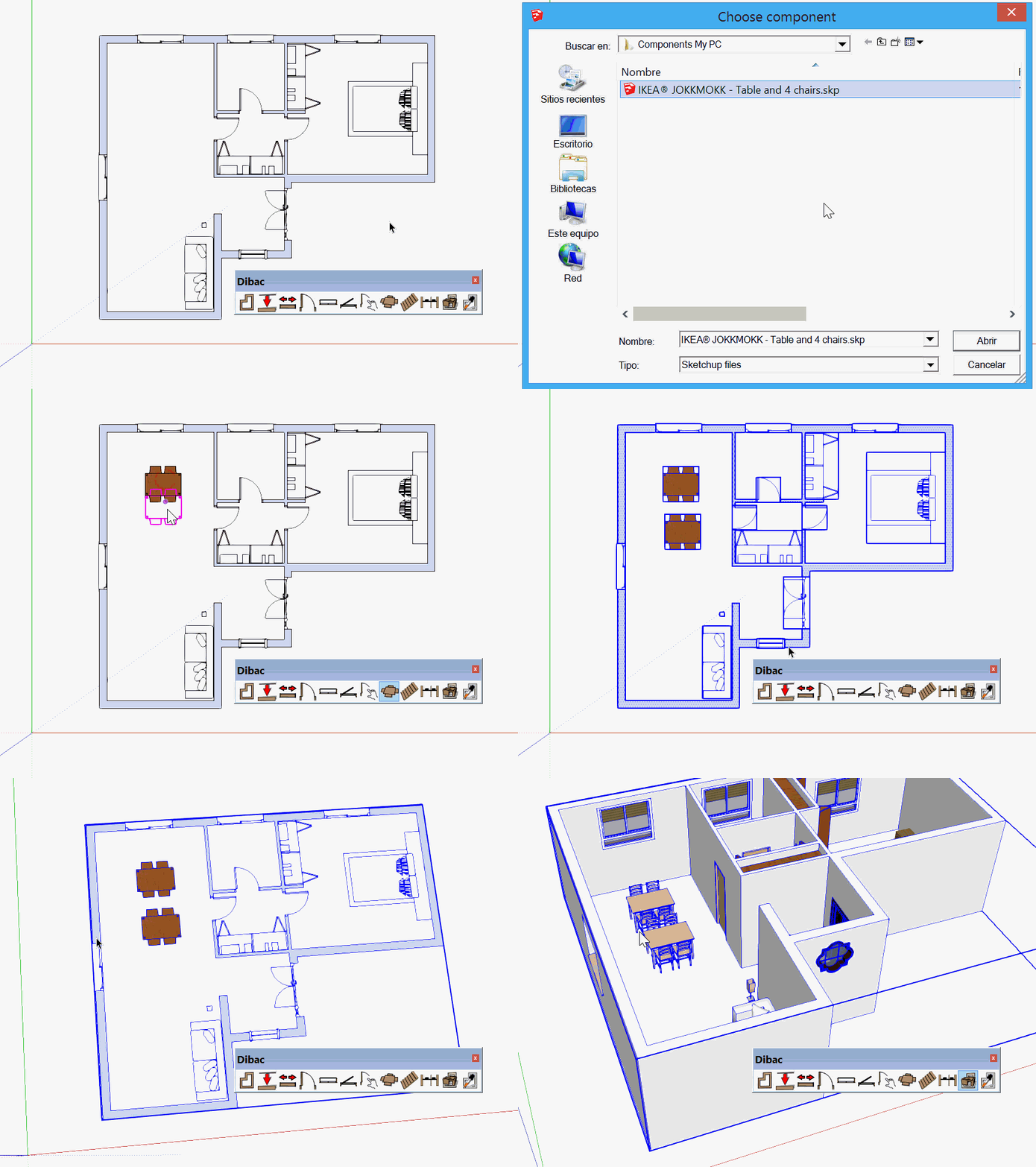
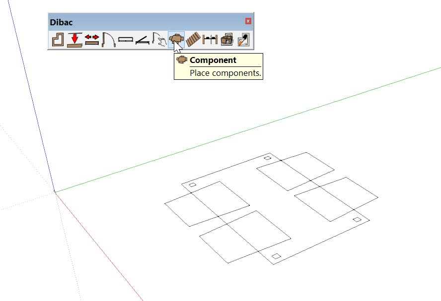
Click on the Dibac COMPONENT tool. In the browser of the computer search for a previously saved component (following our example, the IKEA table with chairs) and click on OPEN.
The component will appear in 2D, attached to the insertion point that we marked out previously by changing the axes. When it turns to magenta simply click to place it on our model.
We must take into account that it is necessary to have at least one wall drawn with Dibac so that the function Convert to 3D works.
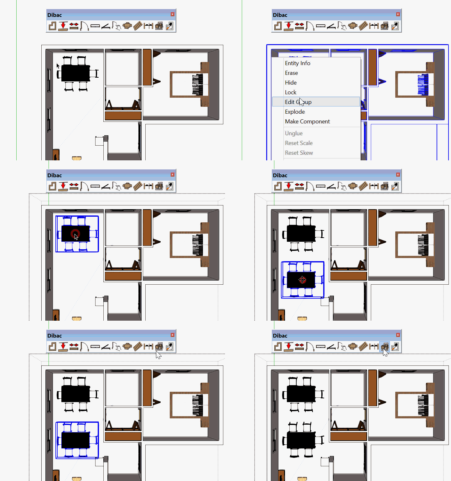
Once we have placed the 2D component, select everything (including the walls) and create a group. With the group created and selected, click on the Convert 2D/3D tool and we will see how our component automatically converts to 3D.
7.3.Elevation of the component
With the ELEVATION parameter we can elevate our component in relation to the floor to a determined distance. (By defect this value is 0 in relation to the origin of the component or the insertion point)
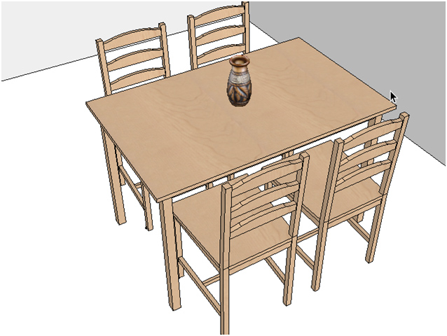
For example, it is very useful if we want to place a vase on top of the table that we previously created. We know that the height of the table is 0.74.
First we select the component tool icon and choose a vase that we have previously saved (by following the same steps as in the table example).
Just before placing it we directly type in the elevation distance in relation to the ground. We type in the elevation 0.74 (which is the height of the table) and press the ENTER key. We will see that our measurements have been saved in the measurements box.
Place the component on top of the table. Once you convert into 3D the component will be 0.74 m from the ground, so it will be situated on top of the table.

7.4.How to change the 2D preview of a component
To begin with, position the component that you want to modify with Dibac “COMPONENT” tool.
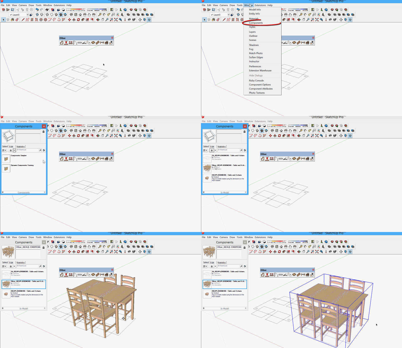
We are going to change the default 2D appearance. Open WINDOW>COMPONENTS.
Once we have the pop-up box COMPONENTS, search for the library “IN THE MODEL”
Three appearances appear for the component in this library:
1- 2D section
2- 2D section + Component in 3D
3- 3D Component
Select the preview that encompasses “2D section + Component in 3D” and move it into the space of the model.
Once it is there, right click on the component and click on “EDIT COMPONENT”.
Inside the editing, if we look closely, we can see that there are two subcomponents: the 2D appearance and the 3D component. With the SELECT tool click on the appearance of the component in 2D and it will be selected. With the SketchUp MOVE tool, move the 2D selection two meters above the green axe.
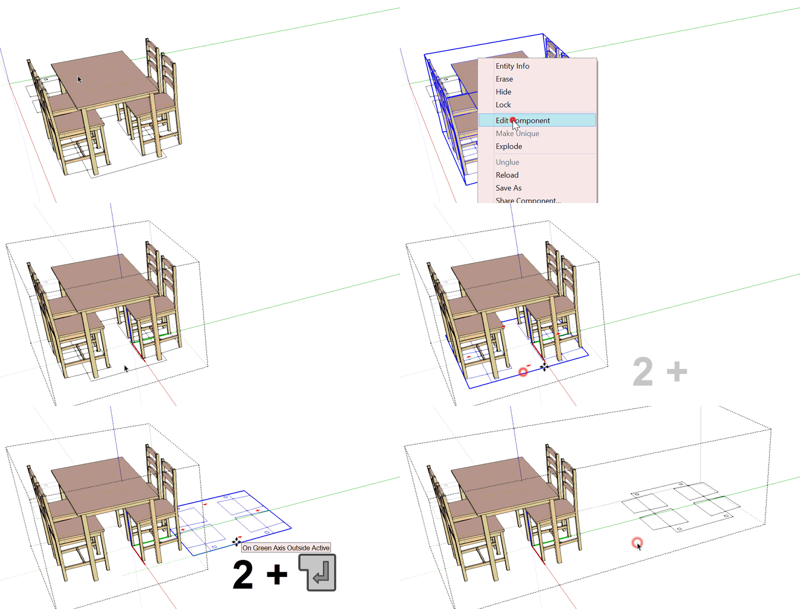
Once moved by 2 meters, edit the subcomponent which is in 2D. In this editing process we make the changes to the 2D appearance that we think necessary. (Delete, add drawing, paint, etc.). Once we have changed the 2D component to our liking, we exit the editing of the subcomponent.
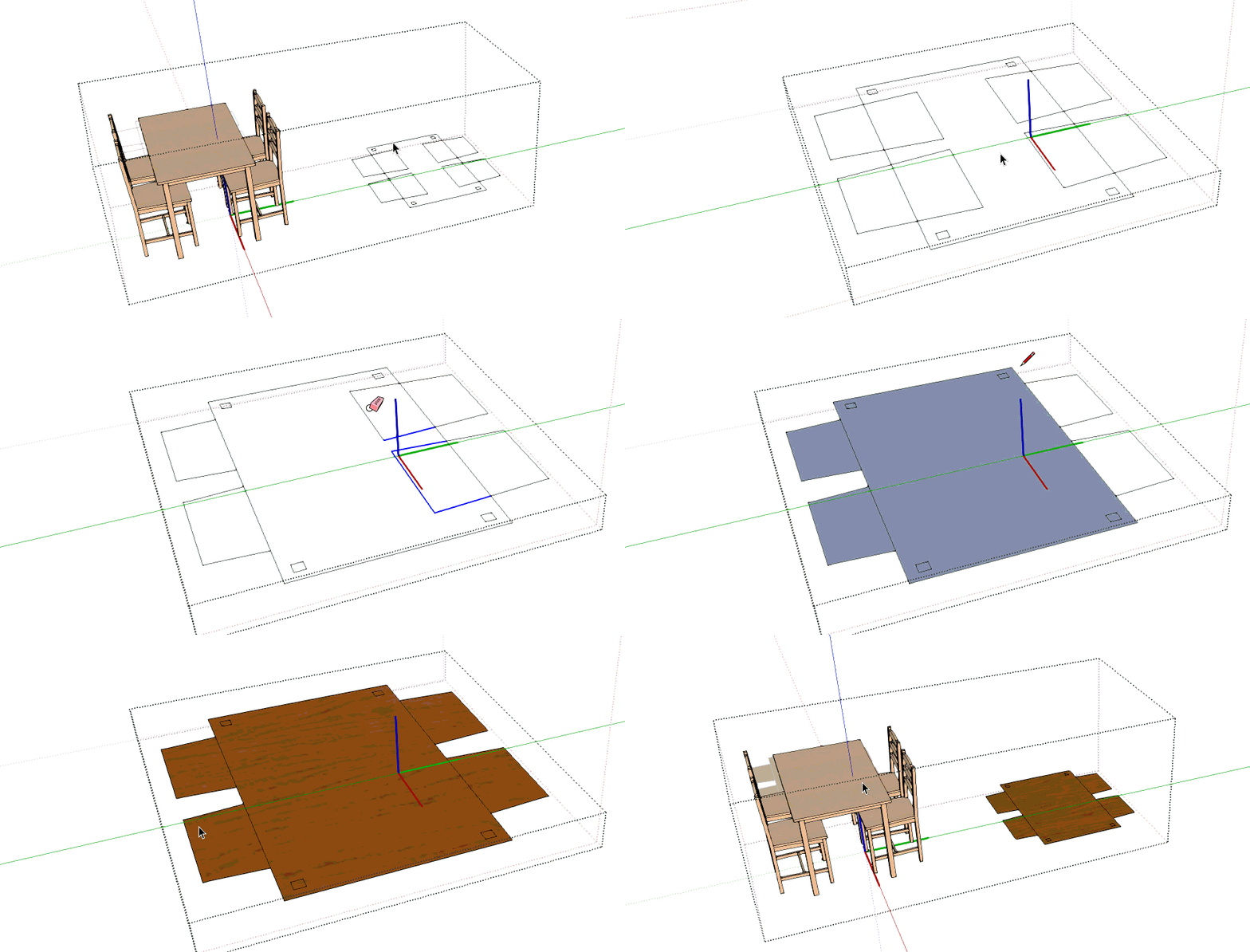
We will continue with the editing of the general component that encompasses 2D and 3D. Select the subcomponent in 2D that we previously modified with one click. Move it 2 meters above the green axe, so that it is the same as it was at the start, just below the 3D of our table. Once it is placed, exit the editing by closing the component.
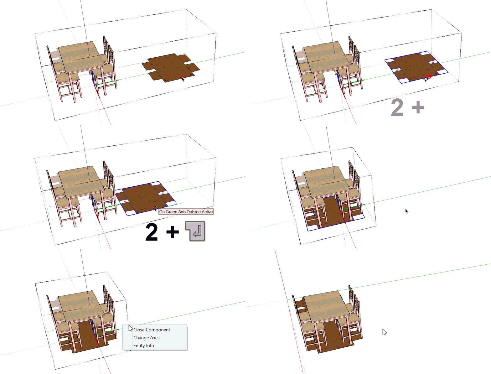
We have already edited the 2D, so we right click on the component and save it again by selecting the “SAVE AS” option. If we want to, we can overwrite the original component that we started with.
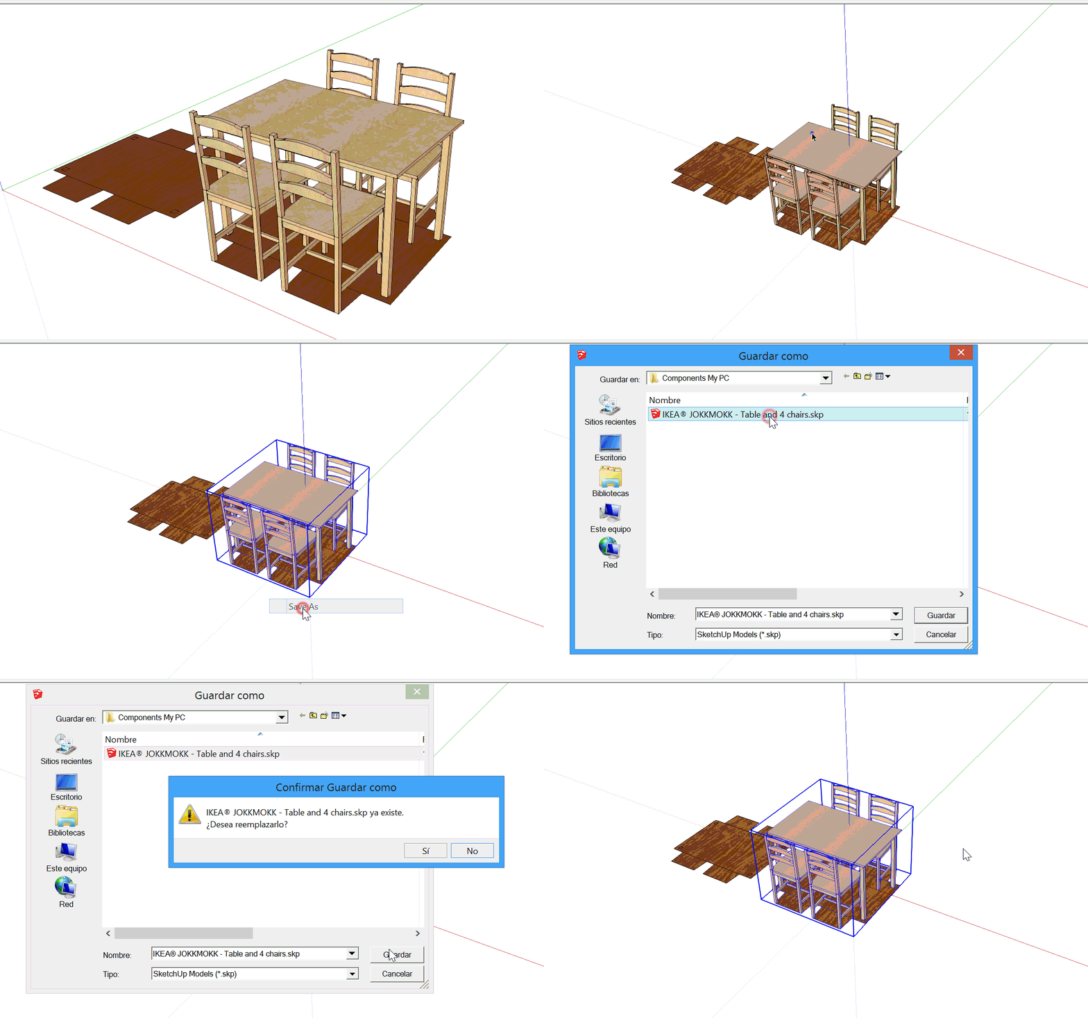
We have now modified and saved the component. Now we can place it with the new 2D appearance using the Dibac “COMPONENT” tool.

8.Staircases

There are two ways to draw staircases with Dibac:
- Starting from zero. Normal staircases, ones with one or several sections, with equal steps and square or rectangular landings can all be created automatically in floor plan and then in 3D.
- Starting from a drawing in floor plan. A staircase is automatically created in 3D, with any type of steps of any shape, be they equal or unequal. All of the steps created will have the same riser height.
8.1.Starting from zero
We’re going to create staircase in floorplan, in order to automatically convert it to 3D.
Select the STAIRCASE icon.
A dialogue box will appear where all of the details of the staircase can be introduced.
- Width: This is the width of the steps and therefore the width of each section of step.
- Height: This is the total height of the staircase.
It doesn’t matter if these are not calculated in the moment of creation, as once the staircase is generated in 3D it is very simple to adjust it, changing the height easily with the SCALE option.
- Tread: this is the depth of the step. Here you can add the symbols “>” (greater than) and “<” (less than).
- Riser: This is the height of each step. Here you can add the symbols “>” (greater than) and “<” (less than).
Step (H+2T): This is the convenient formula for the staircase. With this you can adjust a value, the relation between tread and riser. Once the details have been introduced, press ACCEPT.
We are going to draw a staircase. Place the cursor on any part of the model.
Click to begin and move the cursor to the right (Some details will appear, with the order number and the height of the steps). Just after the sixth step CLICK again (2).
Now change the direction 90° to the left. Move the cursor two steps up and (just after the eighth stair) CLICK again (3).
Finally, change the direction again another 90° to the left, move the cursor six steps up and (just after the fourteenth step) DOUBLE CLICK.
A group will be created with the staircase drawn in the floor plan.
Now you can select it to move it to its correct place in the corner.
Select the staircase group and press the CONVERT TO 2D/3D icon to construct it in 3D.
When a section has been created and the direction has to be changed to begin the second section, this is normally done by complete steps.
The possibility to force the change in direction to a fixed point does exist. To do this, hold down the CTRL key while you CLICK to change the direction of the section.
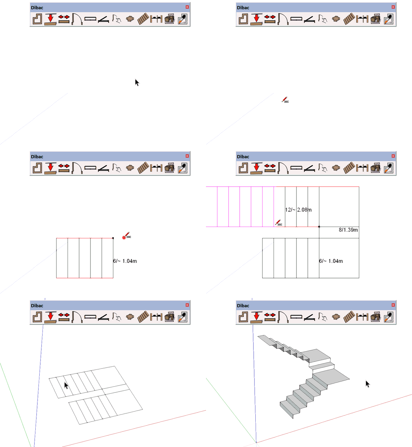
8.2.Starting from a drawing in floor plan
If we have the staircase in 2D, we can construct it in 3D with Dibac.
Before we begin, it is important that each of the steps is flat. To do this we draw on one of the sides using the line tool.
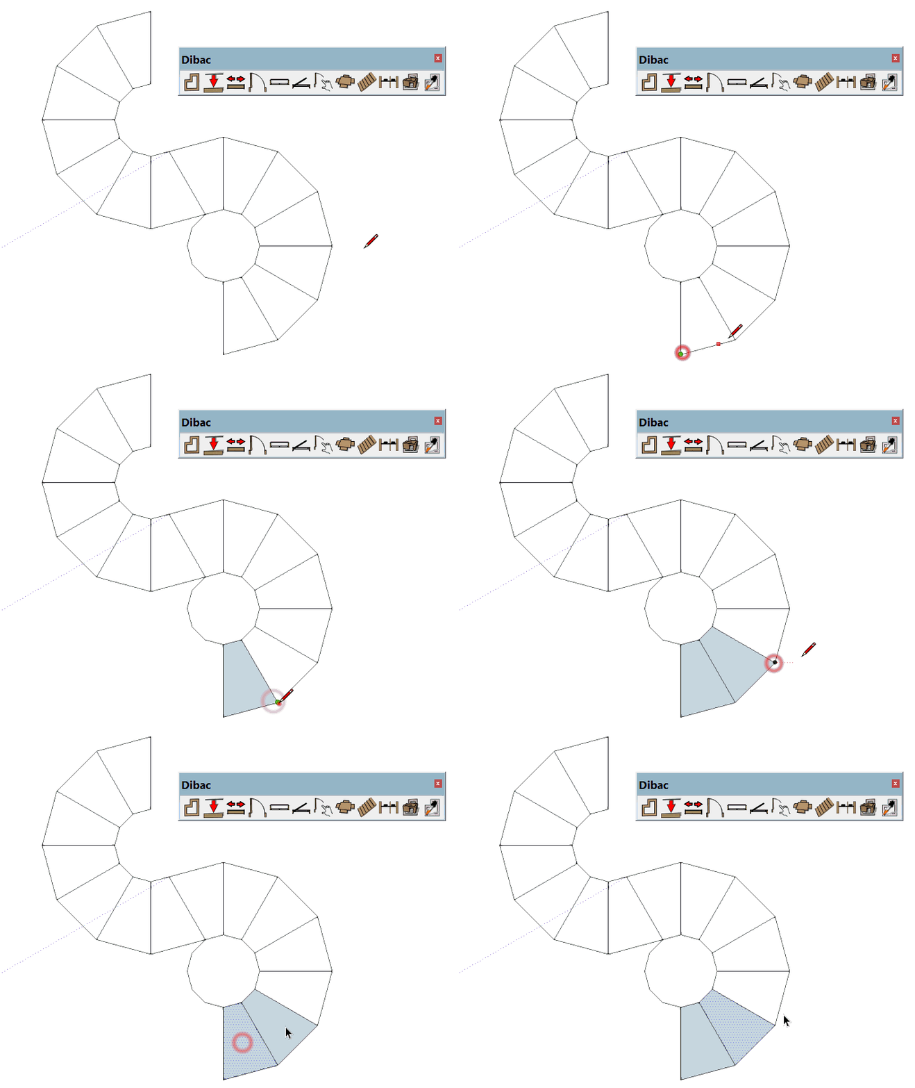
Once the 2D drawings of the staircase are complete, we select the STAIRCASE tool.
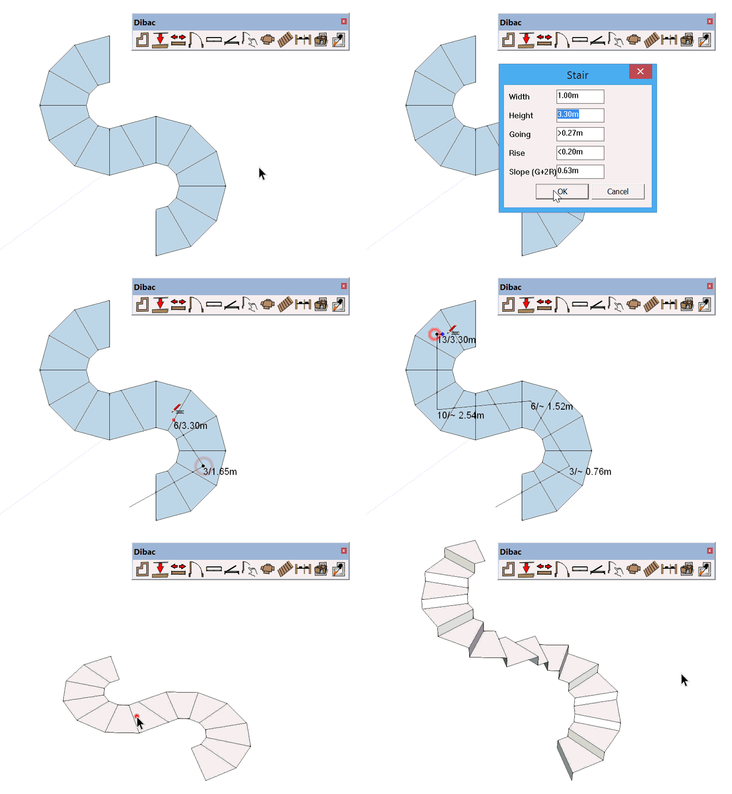
Amongst the different options that are offered to us, we only alter the HEIGHT of the staircase. The rest of the parameters do not have any influence in this case.
Accept the options and double click on the exterior of the staircase to begin.
Move the cursor over each of the steps that we can in a straight line, in an upward direction.
When there is a change in direction, click and move the cursor over all of the steps that go in the other direction, always in a straight line.
Once we have done all of the steps, end with a double click.
The staircase will turn white and will automatically generate a group. If we select this group and click on the CONVERT TO 2D/3D tool, the staircase will be constructed in 3D.
9.Continuous dimension

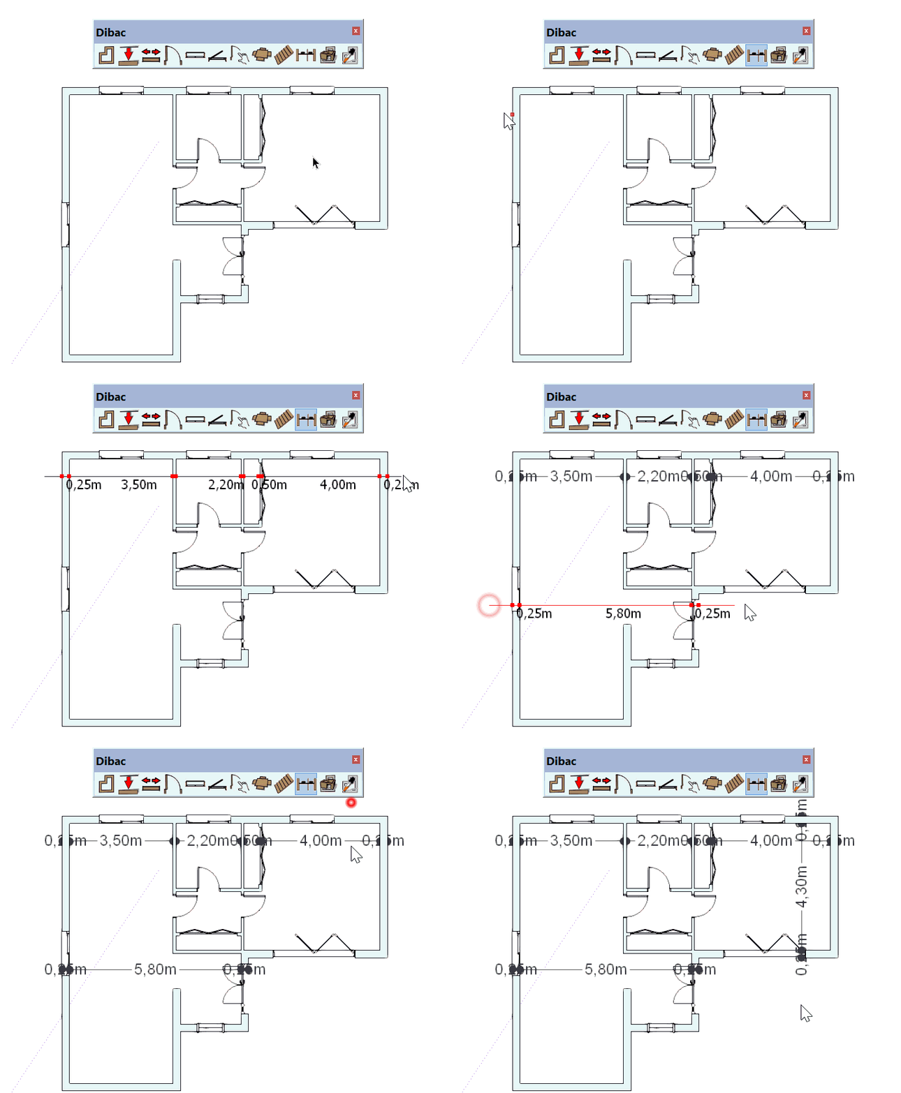
With this tool we can measure a floor plan almost instantly.
Move towards one of the sides of the plan, click once to begin measuring and move the cursor over the part of the drawing that we want to measure. The dimensions will appear, and when we reach the other side, click again to finish.
They will remain fixed, but not permanent. One more click is needed in order to situate the dimensions.
9.1.Minimum length of measurement
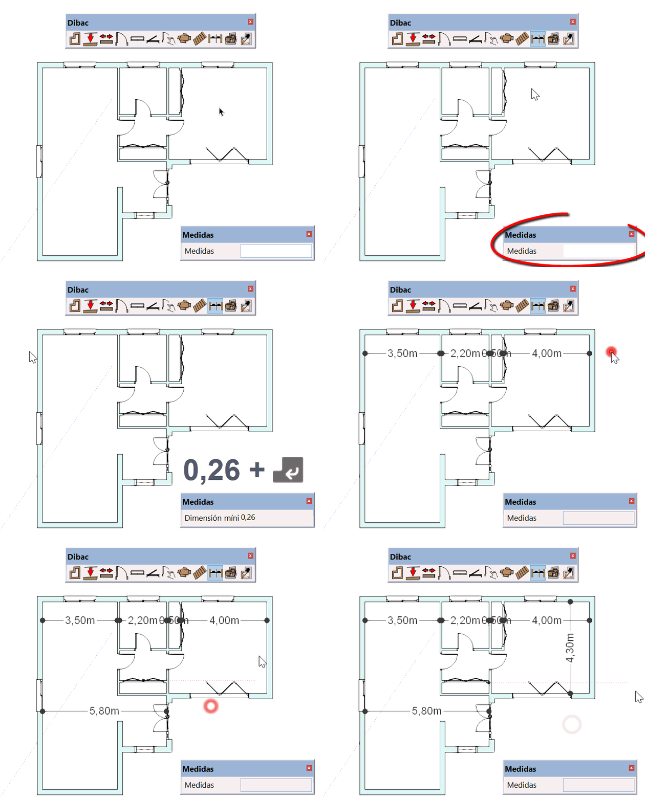
The minimum length that will be measured. That is to say, anything lower than this minimum will not appear in the dimensions.
If we do not wish to measure the wall, which has a measurement of 0.25 m. when we select the dimension tool, we type in directly 0.26 m. and confirm with the ENTER key. Nothing that measures less than 0.25 m. will be measured.
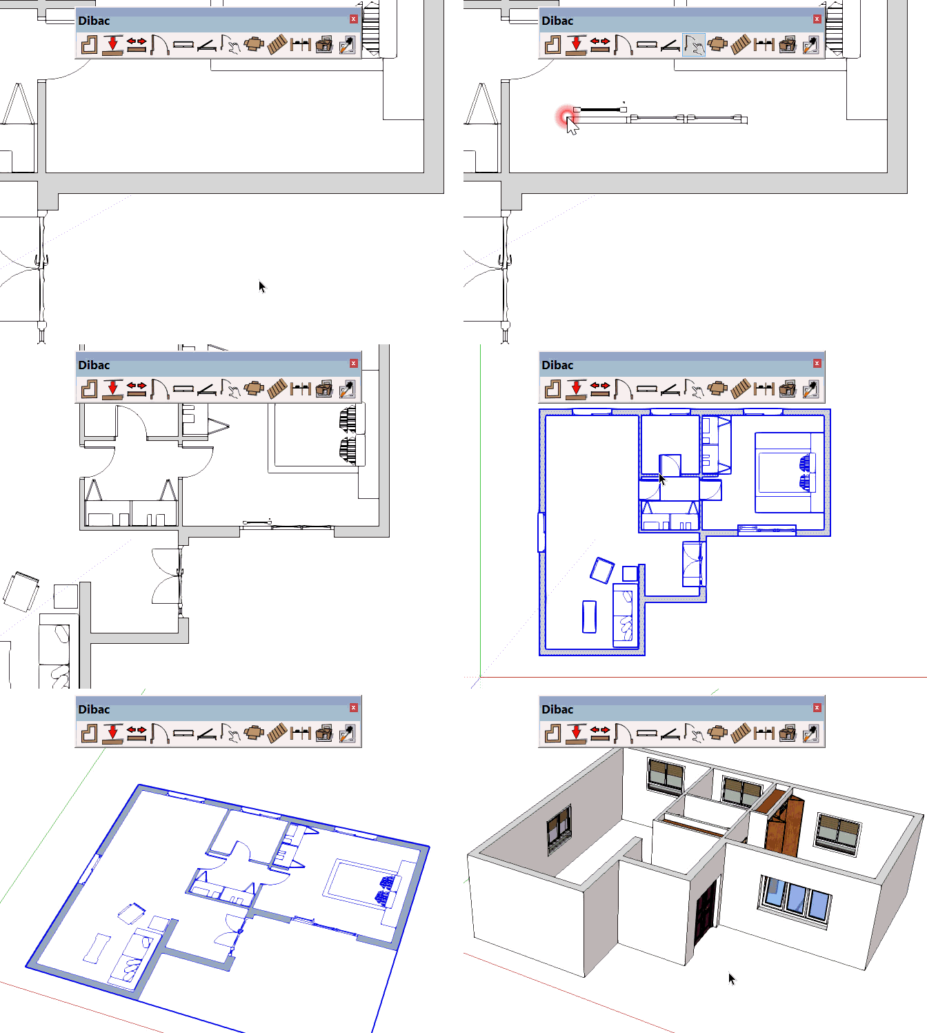
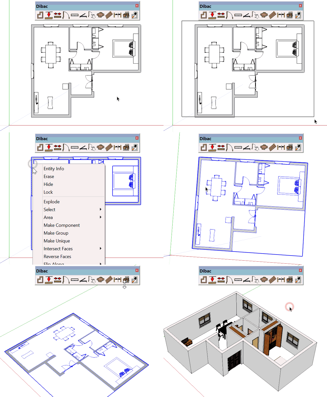
10.CONVERTING TO 2D/3D

To construct a 2D drawing in 3D, FIRST WE MUST GROUP IT.
To do this, we select what we want to convert to 3D, we right click on the selection and select CREATE GROUP.
With the group selected, click on the CONVERT TO 2D/3D tool. Automatically, everything included in the group will be constructed in 3D.
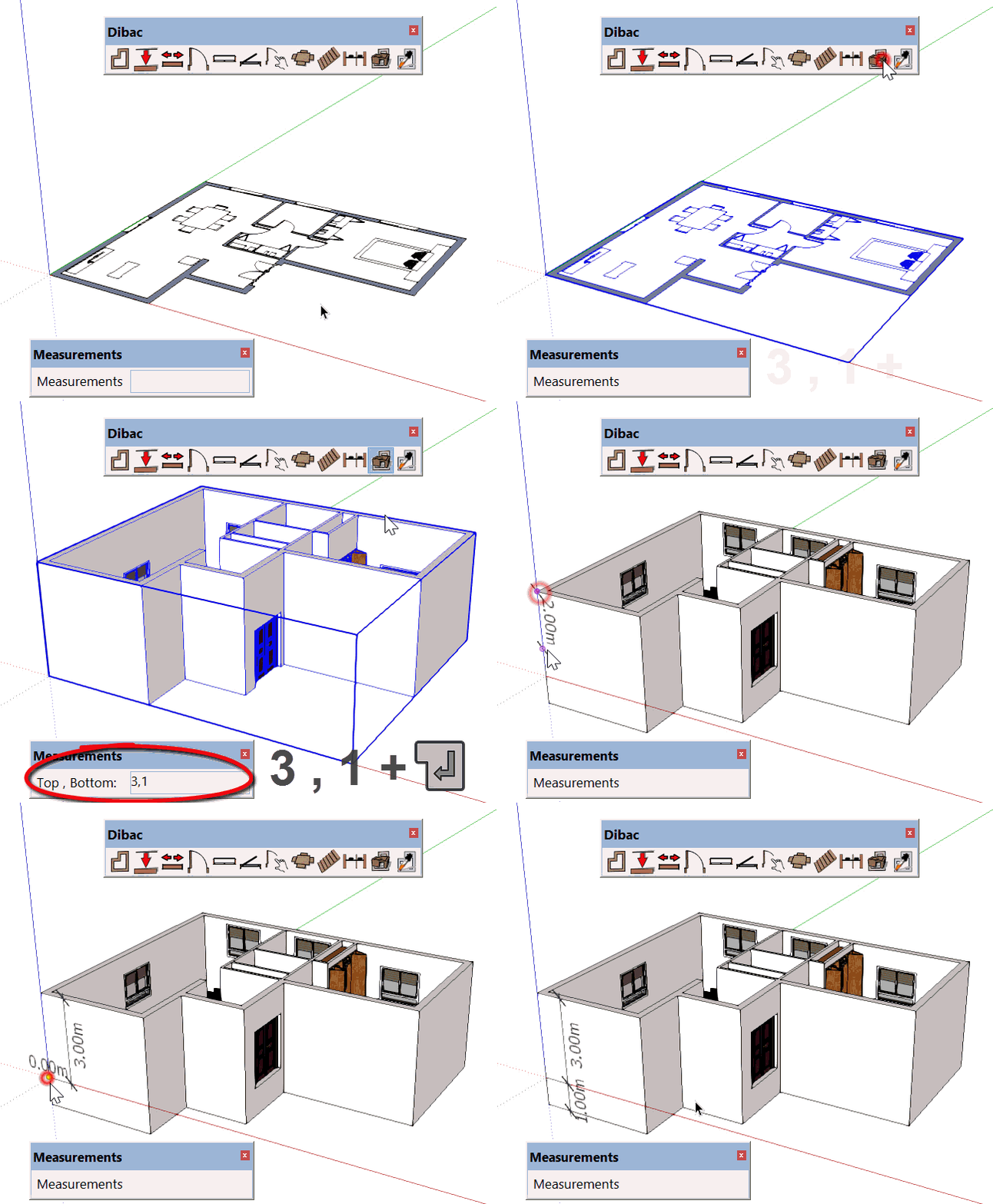
Once we have used the CONVERT TO 2D/3D tool, we can change the height of the walls and also the measurement of their inferior base in relation to the origin.
To do this, once we have constructed it in 3D, we type: Height measurement “semicolon”. Downward measurement (from the origin) and press ENTER.
For example, if we want a wall that is 3 m. high in relation to the origin, and 1 m. below the origin, underneath, we would type (just after constructing in 3D) 3;1 and confirm with the ENTER key. We will see that a 4 m. wall is created, 3 above and 1 below the origin.
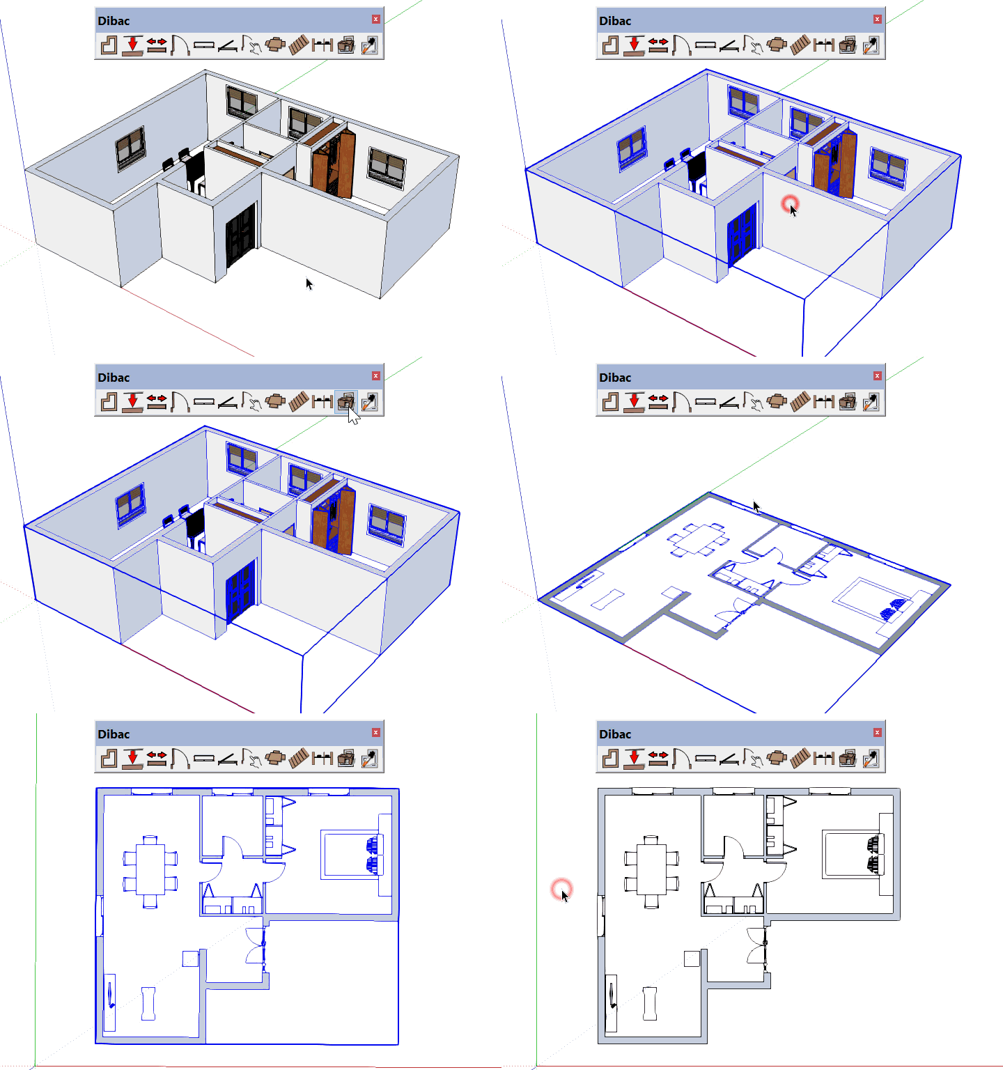
TO GO BACK TO 2D, select the group that we had converted to 3D and press the CONVERT TO 2D/3D tool. It will automatically convert back to 2D.
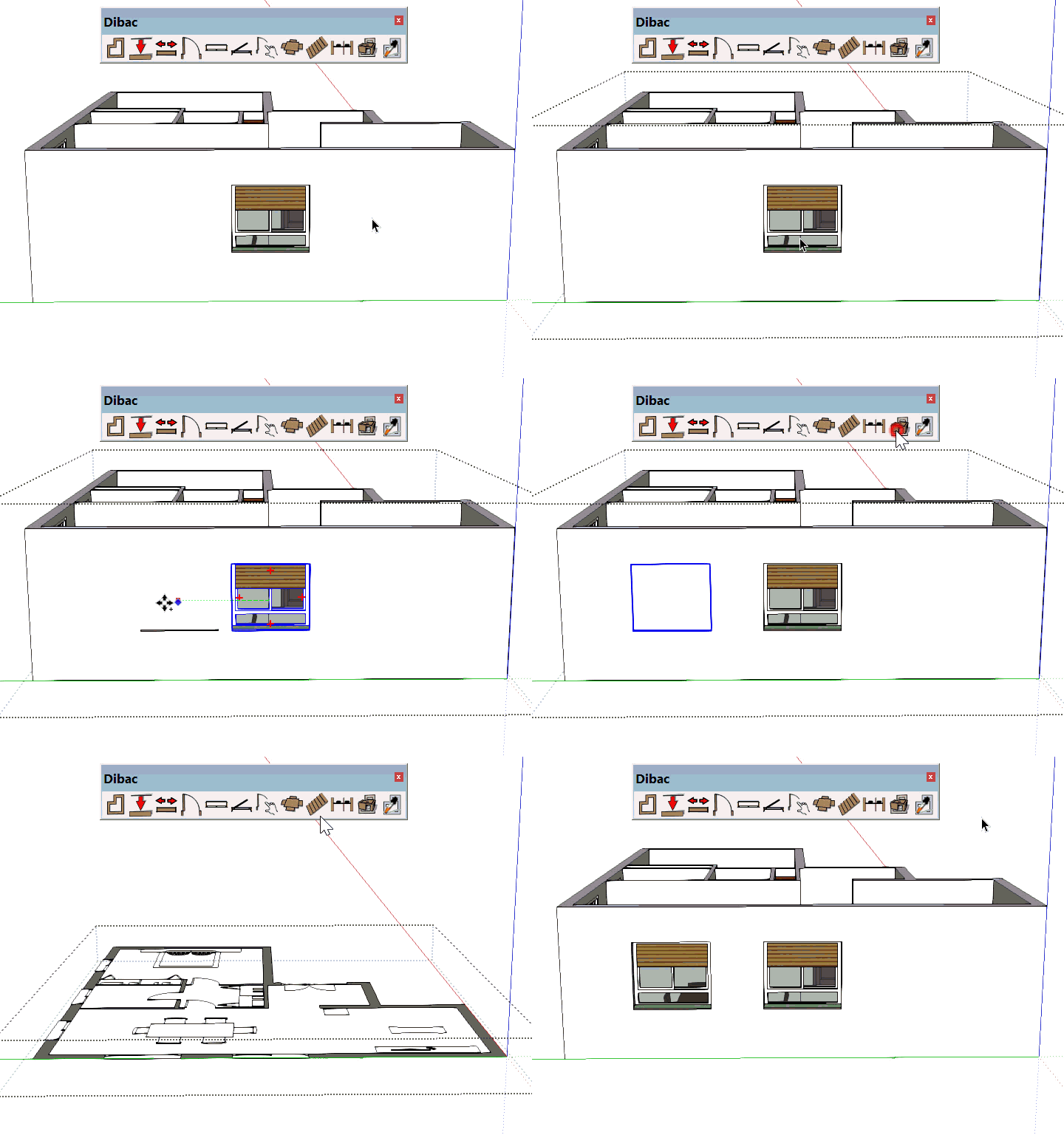
11.Acquiring Dibac elements

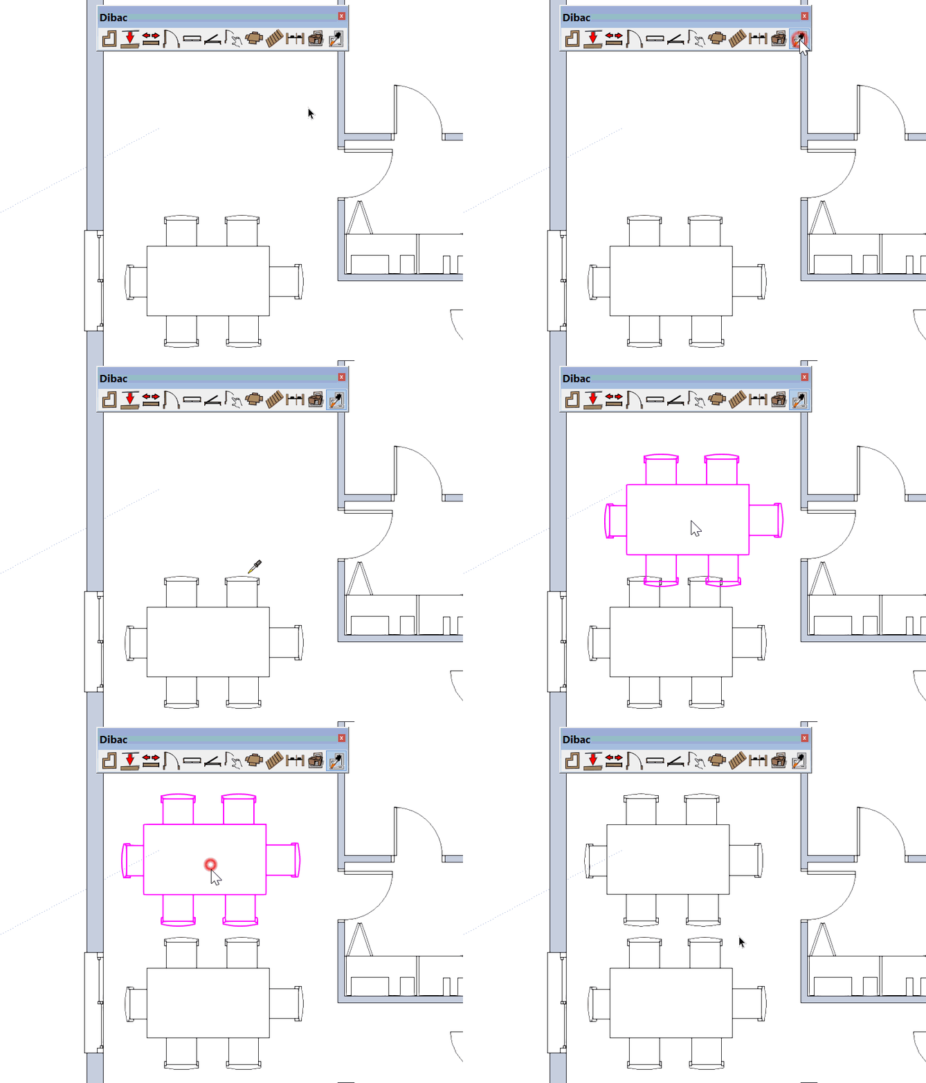
With this tool we can copy the properties of any drawing done with any Dibac tool. We can also select functions, like wall, with all of the attributes of the wall already acquired.
For example, if we use the Acquire tool to select one of the walls by clicking on it, the wall tool is directly activated with the same thickness as the wall that we clicked on.
Another example: If we click on one of the joineries that we have placed in the project, the select joinery tool (door, window, select joinery) is directly activated with the same properties as the one that we clicked on.
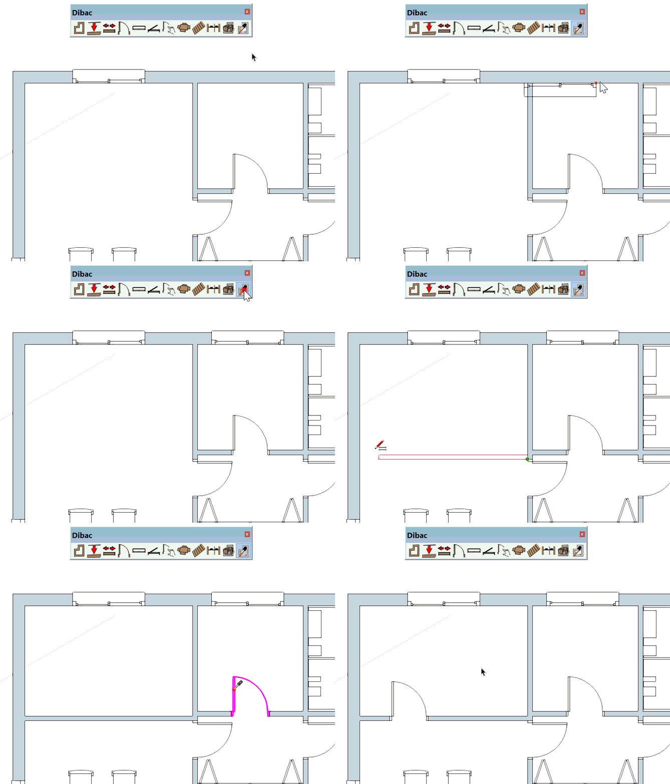
Even if we click on one of the components that we have placed in the project, the properties of this component are directly copied, ready to be placed wherever you wish.
